by Bert Eendebak
1 Introduction
In designing your own guitar personal preferences may play an important role. Do you want to play the guitar yourself? Do you (intent to) play just for yourself or do you need extra volume to cope with other instruments of the band or ensemble you are playing with? During the design of a guitar hundreds of large and small decisions have to be made. Sometimes related, sometimes not. (I have “counted” more than 200 different “decision points”!). To bring light in this complex decision process it is good to be aware of 5 main construction principles that have to be taken into account:
| - Playability | Playing the guitar should be as easy as can be |
| - Constructability | In constructing the different parts no unnecessary difficulties should be encountered |
| - Acoustics | The volume and sound should fulfill your specific and highest expectations |
| - Durability | The performance has to last for at least 50 years |
| - Aesthetics | The guitar should be a piece of art and wonderful to look at |
Sometimes these principles may lead to contradicting decisions and compromises have to be found. However most of the time it is easy to distinguish between “hard” and “soft” demands and to let prevail one principle above other ones. It is part of the design process and fun to make your own balanced decision on conflicting principles. A well-known example of conflicting principles comes up in the design of the soundboard. For a large volume and rich basses you will choose for a light, thin top. That may lead to an instrument with a wonderful sound, a sound however that will last for not more than some weeks because of the deformation due to the pulling forces of the strings. The “balanced” decision that has to be taken on this point and on many others as well will be discussed in the relevant chapters.
Nevertheless there will remain decision points which cannot resolved by calculations, trying to be smart or whatever trick you should have in mind. For this group of “unsolved mysteries” we still have to look to the experience of others (in the past). This is fortunately only in exceptional cases and we will surely draw your attention to it.
Because it is sometimes easier to discuss the design process in terms of specific measures, we will give from time to time specific examples of a realistic design. These examples are taken from some guitars (Guitar EB 2009 and EB 2010), designed and constructed by the author Bert Eendebak.
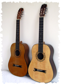
Whenever measures are given in italics they are taken from that design. So keep in mind that those numbers are just examples and can or should be adapted to your own initial choices.
In the description of the design process as given in this article no use is made of computer-based calculations or inside knowledge of mathematics, physics or acoustics. “Design of a classical guitar” is mostly based on the use of common sense, simple logic and of course a lot of reading.
2 On acoustic principles
There is a fundamental difference between a classical guitar and a violin in the way the sound is produced. In both instruments the energy of the vibrating strings has to be transported via the bridge to the soundboard. However finger picking the guitar strings leads to a short excitement of the strings, where in the case of a violin the energy is more ore less continuously added by the fiddle stick. In the case of a violin the vibration of the strings brings the bridge into a movement, perpendicular to the top. Some people describe the same phenomenon for a guitar but in fact it is the wriggling movement of the bridge that gives rise to the waves in the soundboard of the guitar. In designing a guitar understanding this difference is of primary importance.
Because the wriggling movement of the bridge is the main way the soundboard is excited the dimensions and the other characteristics of the bridge of a guitar play a radical role in the design. Because of the limited energy of separate notes of the guitar string every bit of energy should be used to generate the sound we want to hear. But unfortunately the efficiency of that process is low: for a “standard” classical guitar only 5 to 7% of the energy in the string is converted into sound waves. It will be clear that one of the main challenges in the construction of a guitar is to look and fight for every possible improvement of that efficiency. Prevention of every useless loss is a must.
Figure 1: Lay out of the classical guitar
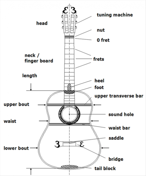
Firstly, the connection points of the strings have to be fixed. The saddle has to be a hard fixed point related to the nut. That asks for a rigid neck, head and nut. In fact also the construction parts, connecting the neck with the bridge and directed parallel to the longitudinal axis have to be inflexible. Even the saddle and the nut have to be shaped in such a way that the string will not lose energy to the construction itself. The bridge itself is only a tool to transport the energy of the strings to the soundboard and it should not absorb any energy by itself. Not by a large momentum of its own and not by internal heat absorption by compressing or bowing motions. So the bridge and saddle have to be as light and inflexible as can be (see chapter 6 .The brigde).
The soundboard forms the vibrating membrane, which makes the music. The waves, introduced in the soundboard should on one side dispose their energy by introducing airwaves, but on the other side fade away slowly to show the desired sustain for the pitch involved. As for the bridge this asks for a piece of wood, that is very light, but with enough strength not to be deformed by external forces it is subjected to.
Here it is important to mention two different construction principles, sometimes described as contradictive. Some guitar builders highlight the essential role of the soundboard by following the frame principle. In that case the guitar body is seen (and constructed) as a solid, inflexible frame on top of which the soundboard is glued. That is in line with the idea that every “unnecessary” loss of energy should be prevented. So the only acoustical function of the guitar body in that case is to reflect the acoustic airwaves. This idea will lead to relatively thick back and sides and makes the construction of these parts relatively easy. However there are some “secondary” effects, which are in favor of a more flexible construction. It is well known, that some famous luthiers in the past, e.g. Torres, Ramirez and Hauser produced instruments with thin and flexible backs and sides. Such an approach has also advantages, of which the following are important. First a thin sidewall combined with a flexible lining allows the edge of the soundboard to turn over a little bit and thus enlarging the “effective” surface of the soundboard. This may give, let it be small, an increase of the sound volume. A second advantage of flexible back and sides is that some standing waves in the guitar body are supported. The end-effect of these different approaches can be characterized as “more volume with flexible linings and more sustain with fixed linings”.
As in life it is good to go for the best in both approaches and instead of choosing one of the two we will look for a combination of rigidity and flexibility of back and sides (see the chapters on top, back and sides).
Vibration modes
For a good understanding of the construction principles as described in this article some basic knowledge of possible vibration modes of the guitar top is needed. The traditional classical guitar top vibrates in many ways, but some fundamental frequencies below 500-600 Hz are of prime importance. These are the (0.0), (1.0), (0.1), (1.1) and (2.0) modes as shown in figure 2.
Figure 2: Primary modes of the guitar top
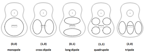
These figures of basic characteristic oscillations will be used for some design steps in the chapters on the sound bar and the back. Interesting and useful background information on these vibration modes, their relationship and effects on the guitar can be found in the reference 1 till 5.
3 Choice of materials
As a starting point for the choice of materials we assume that a classical guitar exclusively is made of wood, with the exception of the strings, frets, tuning machines, nut and saddle. The choice of the soundboard may be among others spruce, cedar, redwood, cypress or mahogany. In many cases the choice is spruce for the “concert” classical guitar or cypress for a flamenco guitar. Within the spruce (Picea) family various variants are used, like Alpine (Fichte), Sitka or Engelmann spruce. The choice is often made based on the availability and price of wood for the soundboard, but the characteristics of the white “Fichte” are clearly different from the harder and finer grained, slightly red-brown colored Sitka. Using a softer material for the top like red cedar asks for a thicker soundboard and adjusted sound bars.
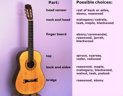
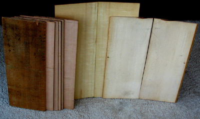
Important are the large differences between different pieces of wood of the same species in view of grain, stiffness, run out, color and figuring. For the top, stiffness and “tap tones” may be the most important ones. For the back color and figuring may be deciding factors. Of course the characteristics of the wood in terms of e.g. strength, hardness or brittleness are important during the construction but have less influence on the main features of the design. The description of the design as given in this article starts from generally preferred materials as rosewood for back and sides, a spruce top, mahogany neck and ebony for the fingerboard and bridge, but other materials with roughly the same strength may be used as well.
Figure 3 : Examples of possible wood choices
4 Main dimensions
Playability
Do you want to have a big guitar or a small one? A big guitar gives you possibilities to end up with a guitar with a large sound volume and strong, durable, sustaining basses. A small one may lose power, compared to the big one, but still have sparkling trebles and be handy to transport. A small one may also be preferred if you have small hands, and find it hard to play specific accords on a big guitar.
Let’s assume that you want to design a guitar, to construct and play it yourself. The first thing you should do is to have a look at the guitar(s) you have already played. Is playing easy? I mean do you have problems with accords, which ask for a large reach of your fingers, especially at the higher positions? No problem? Or do you like to have the frets closer to each other? May be just a little bit. For some people, due to the size or the restricted movability of their fingers a shorter distance between the frets may be desirable. If the distances between the frets are just fine you should keep it that way, so measure the distance between the nut (or 0-fret) and the 12th fret. The scale length of that specific guitar will be twice as long as that length and also the maximum for the guitar you want to construct. Of course if you have no trouble at all playing challenging accords look around for another guitar to try out and to find your own maximum or optimum scale length.
Now for the next step, let’s assume that a large (sound) volume and rich basses are the characteristics you are most interested in. Then you fix the scale length on the maximum you just decided on or just below that. “Small” changes, e.g. between 63 and 65 cm give small changes in volume, but may change a lot in terms of easy playing.
Because it is easy to talk about a specific length and other dimension let’s for the rest of the design process choose for a scale length of 648 mm. But keep in mind that at this starting point of the design you are completely free to make your own choice.
Because the 12th fret is just in the middle between the nut and the saddle the distance between the 12th fret (exact the edge of the guitar body) and the saddle is also fixed. In our example 324 mm.
Other design characteristics that are solely based on playability are the width of the neck and the dome of the fret board (curvature perpendicular and parallel to the neck). Comparative thick fingers are a good reason to choose for a comparative large width for the neck and a stiff, bowed forefinger on your left hand asks for a curvature of the fret board. For these choices please see page neck and head.
Acoustical considerations
The main dimensions of the guitar body however are more based on acoustical considerations. Let’s think about the function of the guitar body as a (Helmholz) resonator. The dimensions of the guitar body or box determine which frequencies are favored for sound waves inside that box. Some people argue that the dimensions should be chosen such that the important tones (to you or to me?) are amplified. Or, in other words, the resonance frequencies of the guitar box should harmonize with the frequencies you like to be sustained at the most. On the other side you can imagine that favoring specific tones will bring the balance of the sound spectrum we strive for, in unbalance. However the practical classical guitar box with its feminine fluent profile has a whole spectrum of inside dimensions and every tone within that spectrum may, so to speak, find its place to resonance for a while. That may be the case, but it is still wise to give the basses we are looking for a preferred status because they are mainly influenced by the main dimensions.
Many designers choose the dimensions of the guitar body like the width of upper and lower bout, waist, height etc. as a fraction of the overall length of the guitar body. Just to realize that the “partials” also easy find a place to resonance for a while.
For that reason we take the distance between the saddle and the bottom as 25% of the scale length. So the length of the guitar body in our case would be 324 + 162 = 486 mm. Taking into account small corrections in view of edges and linings we end up with a total outside length of 489 mm.
Now starting from an inside length of the guitar box, say 486 mm, you may raise a lot of partial lengths, like 1/2, 1/4, 1/3, 2/3, 3/4 x 486 etc. But the choice is not free! The guitar should look like a guitar and for constructability reasons the sides have to follow a smooth curve. Therefore there are only a few possibilities. For the lower bout we choose a fraction of 3/4, for the width of the upper bout a fraction of 5/9 and for the waist a fraction of 1/2.
Again after corrections for linings we end up with the following dimensions (for the EB-guitars):
| Length | 489 mm |
| Width lower bout | 368 mm |
| Width upper bout | 273 mm |
| Width waist | 245 mm |
Dimensions of “Torres-made” guitars
Now having fixed the main dimensions of your guitar you may wonder to what extent these dimensions differ from or are equal to the dimensions of other guitars, preferably those constructed by famous luthiers. So let’s have a detailed look at the main dimensions of guitars built by Antonio de Torres Of the ~ 300 guitars constructed by or under direct guidance of Torres the construction and dimensions of about 80 guitars are reasonably well-known. Derived from ref 11 we put all main dimensions of Torres-build guitars in spreadsheets. A discussion on these spreadsheets, findings and conclusions are published in ref 12. Because it is obvious that a real small guitar (in length) will also have small widths and heights all these dimensions are normalized on a total body length of 500mm. The results are shown in figure 4. The dimensions of the “EB-guitars” are given as dotted lines.
Figure 4: Dimensions of Torres-made guitars; normalized on a length of 500 mm
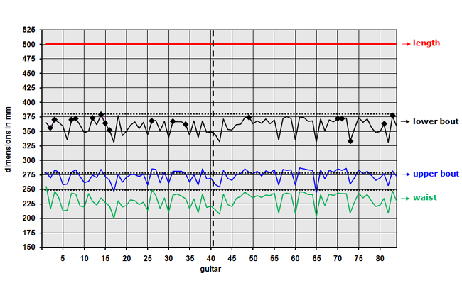
Of a limited number of these guitars (~17) it is known that they were of exceptional class. They are indicated by ♦ in figure 4. It looks like that there is no strong relationship between this high quality and the dimensions. However the dimensions of the group of “exceptional class” fall in general in the upper range. The length of the bodies did not really change during the time (1850-1892) Torres built these guitars and the variations of the ratios between the different width and the lengths were minor.
It is thanks to the curved shape of the guitar body, that allows many different frequencies to feel happy inside, that you can build with large and with smaller bodies.
The height of the body for these guitars always shows the effect that the height at the top is smaller than at the bottom, varying between 5 and 10%. Also taking into account convenience of holding the guitar and the wish to give preference to strong basses the height of the EB-guitars is taken as 90 mm at the top up to 100 mm at the tail block.
The diameter of the sound hole for the Torres-made guitars varied between 84 and 90 mm with a few exceptions up to 95 mm. When you decrease the diameter of the sound hole of your guitar by partially blocking the opening you will hardly be able to hear the difference as long the variation is not too big. That would be a reason to decrease the sound hole diameter to e.g 60 mm. This would contribute to the strength of the upper bout and a little bit to the acoustical performance of that part of the soundboard. However by doing so you will not be able to go for final adjustments or repair activities inside the box. This last point is the main reason that for the EB-guitars a diameter of 88.2 mm (in fact 2/11 x 485) is chosen.
Final decisions on main dimensions
If you wish to have 18 full length frets, as is usual for a classical guitar, and you position the upper transverse bar and the waist bar 5 mm separated from the edge of the sound hole the other main dimensions can be derived easily. In figure 5 below these dimensions as applicable for the EB-guitars are indicated.
Figure 5: Choice of the main dimensions

5 The neck and head
Dimensions
As explained in the chapter on acoustic principles the construction of the neck has to guarantee that under string load the neck deflection will be practically zero. From the standpoint of a design that is based on a connection between nut and saddle firm as a rock the design of the neck itself is relatively simple. If you follow the usual instructions in guitar construction manuals you will end up with a neck that can withstand the pulling forces of the strings without any problem. For an impression of actual deflection it is interesting to look in the appropriate spread sheets in”Left-Brain-Lutheri” (ref.15).
For a more or less standard classical guitar neck (mahogany with an ebony fret board) the deflection, measured in change in the action at the 12th fret is about 0.1 mm, which is no problem to deal with during the construction. The choice of the wood and careful construction of the neck and its connections with foot, heel and fret board has to prevent dimensional changes with time. But that is more of a constructional challenge than a design problem.
In order to avoid buzzing of the vibrating strings against the frets we have to provide enough action (distance between the strings and frets). Too much action however hampers the playability and therefore sometimes guitars are provided with a concave fret board. In ref.13 by Oswald J. Verbejj the author gives theoretical analyses for an optimal finger board curvature. Some of his conclusions were that:
- the optimal fingerboard is slightly concave with positive relief amounting 1/10th of string action at the 6th fret
- the optimal nut height is 1/20th of string action
- the action of an optimal concave finger board may be 27% lower compared to an absolute flat one
These findings are applied for the EB-guitars.
In view of the playability the fret board may also be domed perpendicular to the neck. To what extent is up to the choice of the individual player. The fret boards of the EB-guitars described on this web site have a slight dome. At the position of the high and low E-strings the fret board is thinned with ~1.5 mm compared to the middle of the fret board.
In general, the width and thickness of the neck and fingerboard are chosen in view of the playability of the guitar. From that point of view it is interesting to know how some famous luthiers chose these dimensions. In his book “Making Master guitars” (ref 21) Roy Courtnall gives detailed information on the dimensions of 8 classical guitars, constructed by internationally famous guitar makers. Taken from that reference some dimensions related to the neck and fingerboard are given hereafter (measures in mm).
Figure 6: Explanation of codes used in table with dimensions
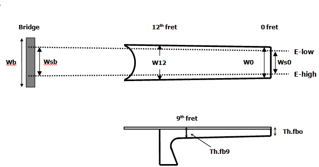
| Guitar | W0 | W12 | Ws0 | Wb | Wsb | Th.fb0 | Th.fb9 |
|---|---|---|---|---|---|---|---|
| Antonio de Torres, 1864 | 49 | 60.5 | 42.5 | 82 | 56 | 24 | 27 |
| Santos Hernández,1933 | 50 | 61 | 41 | 83 | 58 | 23.5 | 25.5 |
| Hermann Hauser, 1931 | 52.5 | 63 | 43.5 | 85 | 59 | 22 | 27.5 |
| Hernandéz Y Aguado,1963 | 52.5 | 62.5 | 45 | 83 | 59 | 21.7 | 23 |
| Ignacio Fleta, 1968 | 52.5 | 62.5 | 43.5 | 80 | 59 | 21.2 | 26 |
| Robert Bouchet, 1963 | 50.5 | 61 | 44 | 81.5 | 56.5 | 22.8 | 23.5 |
| Daniel Friedrich, 1992 | 51.5 | 61.5 | 42.5 | 81 | 57.5 | 21.6 | 21.7 |
| José Romanillos, 1973 | 52.5 | 62.5 | 43.5 | 87 | 59 | 20.5 | 25 |
| EB-guitars | 53 | 59 | 44 | 75 | 56 | 21 | 25 |
The distance between the E strings for the EB-guitars is chosen to be 44 mm at the 0-fret position and 50 mm at the 12th fret position. So the distance between the E-strings at the saddle position is 56 mm and the distance between the individual strings at that position 56/5 = 11.2 mm.
Figure 7: Thickness of the fret board

Position of neck and guitar body
The position of the neck in relation to the guitar body is a more complicated story! There are many variables that are related to the neck-body angle. In figure 8 a schematic drawing of these variables is given.
Figure 8: Position of neck and guitar body
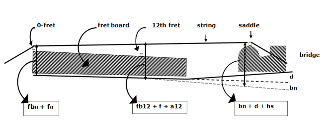
In this figure the following symbols are used:
| fb0 | thickness of the fret board at the 0-fret |
| fb12 | thickness of the fret board at the 12th fret |
| f0 | thickness of the 0 fret |
| f | thickness of all other frets |
| a12 | action of the string at the 12th fret |
| bn | body-neck angle (divergence at the saddle position) |
| d | dome (maximum height of the top above the edge) |
| hs | height of the saddle above the soundboard |
Geometrical laws tells us that the sum of the left and right side of the trapezium in figure 8 equals two times the vertical right in the middle of the trapezium (so exact at the position of the 12th fret). In that way the formula that describes the relationship between the variables can easily be derived from that drawing and reads as follows:
( fb0 + f0 ) + ( bn + d + hs ) = 2 x ( fb12 + f + a12 )
Now the question raises which parameters are decided upon and which will be calculated. Answering that question can be made more easily by fixing those variables, which can be decided on independently of the other decisions. In the following we will describe a possible approach. If view of commercial available fret wire and playability we may fix the following variables:
- f0 = 1.5 mm
- f = 1.0 mm
- a12 = 3.5/4.0/4.5 mm (for the E-high, the G/D respectively E-low strings)
Based on a standard thickness of an unshaped fret board we choose fb0 = 5.5/7/5.5 mm and as a starting point for the construction bn = 0.
By filling in these numbers in the formula we get the following relationships:
- hs = 2fb12 − d + 2 (E-high string)
- hs = 2fb12 − d + 1.5 (G/D strings)
- hs = 2fb12 − d + 4 (E-low string)
In these formulas we can see the relationship between the height of the saddle, the thickness of the fret board and the dome of the soundboard. Some possible combinations are shown in figure 9.
Figure 9: Choice of the dome and height of the saddle
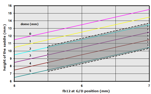
Be aware that figure 9 gives an example of the middle of the fret board and saddle. Based on the assumptions for the dome of the fret board and the different actions for the strings the height of the saddle for the E-high string is 2.5 mm lower than for the G/D strings. The saddle height for the E-low string is 0.5 mm lower than for the G/D strings.
Some constraints in the choice of these combinations have to be mentioned. The dome of the top should be within limits. E.g. not less than 2 mm and not more than 5 mm (see chapter 8 ) . When we choose in figure 9 for a thickness of the fret board of 5 mm (at the G/D position!), we have to realize that at the E string positions the thickness of the fret board at the 12th fret is only 4 mm and at the 6th fret even less (~3.6 mm). This is about the minimum we allow in view of the role of the fret board in strengthening the neck.
With these constraints in our mind we may choose our combination of dome and saddle height within the shaded area indicated in figure 9. For the EB-guitars with a dome of 4 mm and a fb12 of 5.5/7/5.5 mm we end up with a saddle height of 9/10.5/11.5/11.5/11.2/11.0 mm.
During the construction some extra height should be left, leaving room for final adjustment of the action after set up of the strings.
6 The bridge
Introduction
Guitars need a bridge to connect the strings with the soundboard. If the bridge of a guitar is too heavy, too weak or not connected properly to the strings or top it will seriously hurt the acoustic characteristics. Always take care that it will not be the source of any energy loss. Above that, the reaction on the movement of the strings should be as fast as possible. A flexible piece of wood will absorb energy; so we have to look for a light bridge, made of hard material. Ebony and rosewood are most in use. The choice between these types of wood may be influenced by aesthetic arguments. For instance by choosing the same wood for the bridge as for the back, sides, head veneer, the finger board or the sound-hole rosette.
The strings have to be connected to the bridge. This obvious starting point is leading in the design of the length and the profile of the middle part of the bridge. Just take a piece of scribbling paper and draw all kind of different profiles to connect the strings to that midsection at the same time minimizing the cross-section. You will undoubtedly end up with a profile that is very close to the well-known bridge forms in current classical guitars. The length of that middle part will be at least 6 cm and the width (parallel to the longitudinal axis of the guitar) 20 to 30 mm. In the following we will discuss in detail the different aspects you have to deal with.
Compensation
First the location and profile of the saddle have to be chosen. Here the question of compensation is important. Because the fretted strings are stretched the pitch of that string will be slightly increased. By moving the saddle a little away from the head you can compensate for that effect. It looks like a minor problem, but it is complicated because this compensation is different for the individual strings and also because the stiffness of the strings asks for an extra compensation. In a thorough study of Greg Beyers (ref. 7 ) a two fold compensation is recommended:
- Compensation by moving the saddle (contact point) away from the neck, so increasing the length of the string
- Compensation by moving the nut contact point towards the neck, so decreasing the length of the string
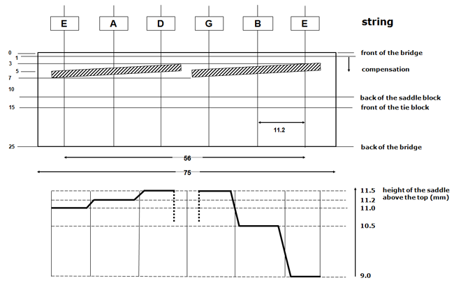
For guitars with 0-fret, compensation at the nut must be the same for all strings. In the design of the EB-guitars this compensation is limited to a fixed shortening of 0.5 mm (by which the 0-fret is moved towards the first fret). For the disgn as described on website the saddle point compensation is more important.
From the calculations and measures as given in ref.7 it can be derived that an arrangement of two straight separated saddles is enough to provide the necessary compensation. This saddle arrangement is shown in figure 10.
For the decision on the height of the saddle see the coming two paragraphs.
Figure 10: Saddle arrangement
The height of the saddle
The width of the middle part of the bridge of classical guitars varies between 25 and 30 mm. This number is important for the efficiency with which the energy of the strings is passed via the saddle to the soundboard. For a specific string the moment (Fstring * hs) should be transferred to waves in the top. With a rigid bridge the energy loss in this process depends on the extent to which this moment conforms to the width of the bridge and the wavelength of the specific pitch in the soundboard. The energy loss during this transport is frequency dependent, but for most of the pitches involved we like to minimize the width of the bridge anyway. The same holds with regards to our wish to minimize the mass of the bridge. From a physical point of view the height of the saddle should be in the same magnitude as the width of the bridge. Increasing the height of the saddle will influence the sound level in different ways. If the height of the saddle is increased from 10 to 20 mm the length of the strings will increase with ~ .25 mm, resulting in a completely negligible change of the sound volume so the most important effect is due to the change in the just called efficiency.
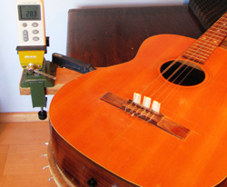
To get an impression of this effect we took an (old!) classical guitar and measured the sound level at a distance of 1 meter from the bridge as a function of the height of the saddle above the soundboard. Figure 11 shows trend lines to give an impression of this effect for the E-low, D- and E-high strings. The trend of an increasing output for higher saddle heights is obvious (as to be expected) but small. Now, if you increase the saddle height of your own guitar for all strings with several mm you have a good chance the bridge will tear away from the top or the saddle will break away from the bridge. Clearly because the design has strived for an optimum bridge for a given height of the saddle. So the best way to come to a “balanced” decision on the saddle height is to optimize the bridge first (see the next paragraph ) and then look for a saddle as high as possible within the applicable mechanical constraints.
Figure 11: Sound level as a function of the height of the saddle

The middle part of the bridge
If you want to optimize the design of the bridge (middle section) the following points should be taken into account:
- The weight of the bridge and therefore the cross section area of the middle part of the bridge has to be minimized
- The height of the saddle has a maximum at the position of the G and D string and a minimum for the high and low E strings (2.5 and 0.5 mm less)
- The stiffness of the bridge has to be much higher than the stiffness of the top, parallel as well as perpendicular to the grain of the top
- The compensation of the saddle as described above, asks for an extra width of the saddle block of ~ 2 mm
- Any slippage of the string over the top of the saddle should be avoided. In that respect we will look for an increased (min. 30°) angle at which the string leaves the saddle top and for an extended contact at the top of the saddle.
The length of the middle part is based on the distance between the strings. For a classical guitar that distance varies between 40 to 45 mm at the 0-fret position and increases to about 57 mm above the bridge. The choice of these numbers has to be based on the playability of the guitar for the future owner. For the EB-guitars these numbers are 44 and 56 mm.
To avoid a weak saddle to bridge connection the total length of the middle section has to be at least 20 mm more (than the distance between the E-strings), so a length of ~ 75 mm is advised. The width of the bridge for the EB-guitars is 15 mm for the saddle block and 10 mm for the tie block, resulting in a total width of 25 mm. The outcome is a relatively high saddle, preferably as high as the strength of the saddle-bridge combination allows.
Figure 12 shows a profile of a bridge as is used in current classical guitars and a second one in which is strived for a minimum cross section within the constraints mentioned above.
Figure 12: Cross sections of the middle part of the bridge

The cross section of this middle part is decreased from ~1000 mm2 (usual lay out) to ~600 mm2 for the optimized cross section.
Wings
The pulling force of the strings has to be guided to the guitar body. That is the main reason that a bridge has to have “wings”. If you have some experience in repairing old guitars, you know that a rather usual failure is formed by cracks in the top, just at the end of the wings. The shorter the wings the more risk you run in this aspect. A general rule sometimes mentioned is that the length of the bridge should equal about three times the length of the central part. Three times 7.5 cm makes a total width of 22.5 cm. In order to decrease the possibility on cracks in the top at the end of the wings it is advised to taper the thickness at the end of the wings (last cm) to the same thickness the top has at that place or less.
If you build a guitar with an arched top the bridge has also a function in retaining the desired arch. This can only be achieved when the stiffness of the bridge is clearly larger than the stiffness of the top (perpendicular to the longitudinal axis), which in itself is in contradiction to the desired homogeneous flexibility of the top. Therefore the added mass of the bridge has to be compensated by thinning locally the thickness of the top.
An important starting point in designing a bridge has to do with acoustics. The main function of the bridge is to trig the vibration of the top. Now looking at the main wood resonances (0.1) and (0.2) (see figure 2) it is obvious that a bridge with long wings will hamper these resonances. Applying the 1/4 principle (see the chapter on the sound board ) we would end up with a total length of the bridge of 18 to 19 cm. This looks a little bit short compared with the “usual” 20 cm but it is better from an acoustical point of view and allowable as long as we make sure that gluing the bridge on the top is executed professionally.
Finally some words about the form of the wings. Almost all designs, ancient as well as modern, show symmetric wings, in most cases thin, with a cross-section of 20×3 mm and more or less rounded at the top and at both ends. One clear exception is the so-called Kasha-bridge (see ref 8 and 9 ) that has a much broader wing at the bass side. The reasoning behind this is that the bass strings introduce the lower frequencies, so the longer waves in the soundboard. An argument to the contrary is that measurements shows up to ~500 Hz perfect symmetry of the Chladni patterns (see ref 5 and 9) and moreover that the bridge is stiff enough to transport all low frequency waves practical without loss to the treble side of the top. Experience falls too short to decide upon, but in my view the argument of the Chladni patterns does not hold. It is the symmetry of the soundboard itself that leads to these symmetrical patterns. Also the argument of the stiffness of the bridge is questionable. If the bridge would be 100% stiff and the soundboard almost symmetrical, the broader part of the bridge could be placed on the treble side as well.
In spite of all those arguments having a bridge with a varying width makes sense. The width of the broader part of the wings is more efficient in starting the low wood frequency waves. With an a-symmetrical top (a-symmetrical in thickness and/or sound bar pattern) it is not logical to go for a symmetrical bridge. First because of the role the bridge plays in strengthening the top and secondly because of its function in triggering the whole spectrum of sound waves in the top. To trigger the main wood resonances and keeping the 1/4 principle in mind (see page The soundboard), the width of the wing on the bass side should be between 25 and 40 mm. All experiences in the past indicate that it is not a big deal to vary between these numbers as long as you keep in mind: as light and inflexible a possible.
Bridge patch
Parallel with the design of the bridge you have to decide on the use of a bridge patch under the bridge. A bridge patch is a construction bar, glued underneath the top, exactly under the bridge. Sometimes the patch is made a little longer than the bridge itself to prevent crack forming in the top. You may wonder what the advantage is of a bridge combined with a patch, compared with a bridge without such a patch, but with a thickness that is increased to end up with the same strength as the combination. In my opinion there are no advantages at all as long as you taper the end of the wings. And therefore I do not recommend the use of a patch. The bridge itself should do the job.
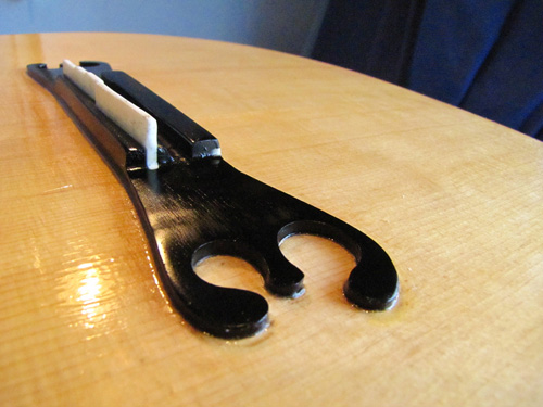
In figure 13 an example is given of a bridge which is designed according to the principles described and applied in the construction of the EB-guitar series.
Figure 13: Bridge of the EB-guitars
Finally, if you like to decorate the soundboard by adding elegant curly wings like those in use in baroque guitars: no objections. But unless these extensions also have a different function as a construction or sound bar they should be thinned (say less than 0.5 mm) in order not to hamper the flexibility of the top.
7 Construction and sound bars
Sound bars have the function of leading the vibration of the bridge to all parts of the soundboard. A second function may be to separate the soundboard in different parts to optimize the response to specific frequencies.
On sound bars there are decisions to be made on profiles and cross sections. It will be clear that the strength of a sound bar and certainly that of a construction bar has to dominate the strength of the plate it has to strengthen. The resistance against bowing of a right-angled bar is given by the formula:
R = 1/12 * w * h3 (see e.g. ref 15 )
with:
w = width of the bar and
h = height of the cross section
In choosing the shape of the cross section for the bars there are several points to consider:
- The bars should be as light as possible, at least those which are connected to the soundboard and the lower part of the back.
- Construction bars should just be stiff enough to fulfill their strengthening function.
- If you want to increase the strength of a bar increasing the height is much more effective than increasing the width.
- In order to avoid twisting of the bar the height/width ratio should be limited (to ~4).
- The maximum pulling forces will be located in the top of the bars. So the cross section should not be decreased towards the top.
- The bars have to be glued on the plate. If you expect (may be during the lifetime of your instrument) unavoidable strong local forces you should aim for a large gluing surface.
- Depending on the expected bowing forces the height of the bar should vary along the length.
Based on these considerations there is playing room for the choice of the cross section, but only within a narrow scope. In figure 14 examples are given of cross sections and profiles based on the aforementioned starting points. For the large cross bars the profile shown in figure 14 and indicated as “flattened pawn” should be aimed at, but of course this profile will gradually flatten at the ends.
Figure 14: Construction and sound bars
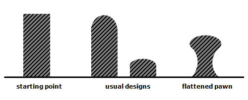
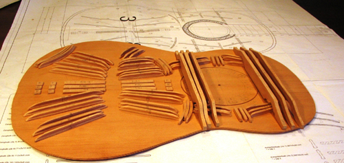
In the construction of the EB-guitars all sound bars are based on the flattened pawn contour adjusted to the specific function and location of a sound bar. The sound bars have a width of 3 to 4 mm and a waist of less than 3 mm. The maximum height of these sounds bars is 5 to 5.5 mm, decreasing at the end of the sound bars. An impression of the application of these sound bars is given in figure 15.
Figure 15: Application of the flattened pawn bars
Bars from scrap
Many luthiers use scrap material from the top, back or neck for making construction or sound bars. From figure 16 you can see in which ways this can be achieved. Starting with a quarter sawn plate, as indicated in this figure there are two ways to cut these bars. If we assume that the height of the bar is more than the width we can take the height in the radial direction (bar 1) or in the tangential direction (bar 2).
Figure 16: Bars from scrap
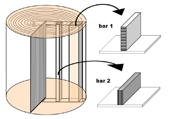
Now the question arises which way is the best: bar 1 or bar 2? Measurements show that it is not possible to measure any difference in elasticity or strength between two identical bars which are coming from the radial or tangential direction. So the pros and cons for using bars of type 1 or type 2, concerning strength and acoustical properties are negligible. Swelling and shrinking due to changing moisture conditions however will be less for bar 2, at least for top wood. This should be the main reason to cut sound bars in the tangential direction, so perpendicular to the plain of the top. For practical reasons an exception can be made for the main traverse bars at the back and above and below the sound hole because their height is more than the thickness of the standard available tops and backs.
8 The soundboard
Nothing is simpler then the construction of an absolute fabulous sounding guitar! Just buy yourself a top of good-quality spruce, thin it to a thickness of “let’s say” 0.5 to 1.0 mm. Put it on an existing or just made rigid guitar box. Put the strings on and you will not believe your ears! But within days you will not believe your eyes too! Because of the pulling force of the strings the top will curve soon – making the guitar false and unplayable. It is the well-known fact that in this case the constructional demands are in contradiction to the musical demands. Here it is impossible to prefer one principle above the other. We have to look for an optimum sound within the constraints prescribed by the laws of strength and playability.
These constraints cannot be described in terms of ultimate keeping qualities or in terms of detailed dimensions of plates, construction bars et cetera. On the one hand because of the many variables at stake. On the other hand because a specific strength can be achieved in several ways. For the soundboard you can improve the strength by the choice of the wood, by doming the top, by less thinning, by adding construction bars, by increasing the cross section of planned construction bars or by using the planned sound bars for construction purposes as well. In the description of how to make successive decisions in this context it is assumed that the construction reflects the idea of having a strong and rigid upper bout and a flexible lower bout. So the top of the lower bout forms the “effective soundboard” for almost all frequencies (say up to 1500Hz.) The waist bar, just under the sound hole, borders this soundboard. Sometimes this approach is referred as “the upper bout is structural and the lower bout is acoustical“.
In going through the design process this black/white scheme should be used with care. Especially for the higher pitches the upper bout should be used to create places for characteristic oscillations. This “dual purpose” approach will be worked out in this paragraph. Apart from which approach you favor the best conditions for resonance are still given by a soundboard having a large number of natural vibrations over a range that includes all the harmonics produced by the strings.
At this moment it is good to keep in mind the difference between construction bars and sound bars. The function of construction bars is to strengthen the construction. To guarantee the guitar body can withstand foreseeable outer forces, but also to keep the soundboard in shape for many, many years. Sound bars have the function of leading the vibration of the bridge to all parts of the soundboard. A second function may be to separate the soundboard in different parts to optimize the response to specific frequencies. So the sound bars, by their positions divide the soundboard into smaller parts that optimize higher characteristic oscillations. In other words: every frequency or partial should find its own piece of soundboard. Now for practical reasons it is desirable to take into account, that sound bars also have a function in strengthening the soundboard and doing so relieve the task of construction bars. The other way around construction bars may play a role (but a very minor one) in the acoustical tasks of the sound bars. In fact the combined task of construction and sound bars, together with the top in maintaining strength and optimizing acoustical functions is so complex that it is, at least in this time for mortal beings, impossible to come up with one unique mathematical solution for an optimal design.
The practical way is a “fix and improve” approach. That means: Find a solution in which the most important design principle (for that part of the guitar!) is optimized and then fine-tune that solution by taking other design principles into account.
Hereafter we will describe the design of the soundboard by taking the following steps:
Boundaries of the soundboard
The lower part of the soundboard is bordered on three sides by the outline of the lower bout and on the fourth side by the waist bar. This border can be more or less fixed. If the glue edges are rigid and the sidewalls are strong then the edge of the soundboard is clamped as firm as a rock and prevented from bowing there. On the other side if the sides are thinned and the glue edges tiny the top edges are allowed to bow. If you follow that approach the “effective” surface of the soundboard is enlarged. The effective width of the lower bout may be enlarged with 5 to 10 mm. That is not much but still worthwhile. It is hardly possible to use the same idea for the waist bar. The main function of that bar is to build a fixed construction point to connect both sides to each other and to strengthen the top, which is “damaged” by the sound hole.
Selection of the sound bars
As explained in the chapter on acoustic principles the first function of the sound bars is to distribute the vibration of the bridge to different parts of the soundboard. This can be achieved in different ways, e.g. by a few sound bars or by many more flexible sound bars. The sound bars may consist out of one bar or may consist out several bars, which pass on the sound waves to each other. Now let’s first discuss this last idea more in detail. From the discussion on the bridge remember that the wobbling, waggling movements of the bridge start the sound waves in the soundboard. It is possible to enhance the distribution of these waves with the aid of long sound bars that pass over and/or are connected to the bridge as e.g. in the case of the fan-wise design with 7 sound bars as commonly used by Torres. A second, different approach is to take the bridge as the starting point of the sound bar, using short, less flexible sound bars as e.g. in the Kasha-design. The design approach as described on this web site follows for a part the second approach. The reason for that choice is that the top plate should have the largest possible number of modes of oscillation and the idea of “mini soundboards” can be worked out more easily. Moreover the flexibility of the soundboard can be better adapted to the main wood resonances.
The second function of the sound bars is to divide the soundboard into “mini soundboards” suited to resonate at different frequencies. That is less obvious than it sounds. Also a top, without any construction or sound bar gives room to all kind of small waves or higher partials, with the restriction that the boundaries will act as nodes for those waves. In that way, adding “sub boundaries” may improve the acoustic properties of the top but only if these sub boundaries lead to suitable mini soundboards and does not stiffen the top in a negative way or at the wrong place.
The natural frequency of a plate is dependent of the elasticity (Young’s modulus), the density and the dimensions of that plate:
Frequency ~ h/L2 * √E/d (see e.g. ref.15)
With:
E = Young’s modulus (constant for a given material)
d = density
h = plate thickness
L = width of the plate
So a plate with a width, that is 2 times smaller, will have a resonance frequency four times higher.
Now the main air resonance frequency of a classical guitar is very close to the lowest open string note (E). The lowest wood resonance peak (0.0) is higher, depends on all kind of material and construction details, but is in the order of ~200 Hz (see ref 2). So this frequency is the fundamental frequency of a soundboard with an effective width (L) of about 36 cm.
Then the high pitch (~600 Hz) will ask for a resonance area of 36 x √200/600, so in the order of 20 cm. Another example is the area in the upper bout on both sides of the sound hole. These regions can be regarded as mini soundboards with an effective width of ~7 cm. The thickness of the top in that area may be 30% more than that of the lower bout. So the resonance frequency will be in the order of
200 x (36/7)2 * 1.33 = 7000 Hz.
Frequencies of that order are still important. Jansson (ref 5) stated: Sounds filtered to give components only below 2000 Hz sound dull and hollow.
For that reason, in this first approach we will provide for several mini soundboards of that size and the way these mini soundboards are stirred.
Creating mini soundboards with varying size (length, width, thickness) to enhance as many harmonics as possible is not enough. The desirable characteristics of a classical guitar are loudness, sustain (duration) and the evenness over the range of notes. This task looks more complex then it is. Creating a limited number of mini soundboards, clearly separated in their natural frequencies is generally sufficient to create a large number of possible places for the whole spectrum of different tones. This is caused by the variations in the dimensions of the different mini soundboards and by the broadening of the resonance peaks.
The soundboard is usually made out of two pieces of wood. The seam between these two top halves needs some reinforcement. Of course the grain of these strips has to run perpendicular to the grain in the top or back. This cross banding is applied to reduce the chance of a split along the centre joint. If appropriate we will make use of that enforcement in such a way that it functions as a sound bar as well. The first task of the sound bars is to transmit the rocking movement of the bridge to those places of the soundboard that are meant to be the playing field for specific frequencies. In doing so an important question is whether you can better reach that goal with a one-piece sound bar or with a chained sound bar, that is a combination of several sound bars in succession. Take for instance the part of the top above the waist bar, or even above the sound hole. Those parts were predestined to enforce higher pitches (above ~7000 Hz). If we use a one-piece sound bar running from the bridge, passing underneath one or two arched crossbars up to those parts, we stiffen the top all along that road at cost of the basses. Making those sound bars flexible can hardly compensate that disadvantage and of course makes them less effective in connecting the bridge with the upper bout. In this case a chained bar, consisting of three smaller sound bars, one after the other, will have almost the same efficiency in stirring up the upper bout regions, but will be much better as far as the flexibility of the main soundboard concerns.
Positioning of the sound bars
At this moment we are ready for a first approach of the position of the sound bars. The first one is located in the middle along the seam. Two chained bars are heading for the openings in the waist bar. Two extra bars on the outside to reinforce the top and fulfilling the wish to homogenize the top and to provide some mini sound boards. The sound bars below the bridge are almost mirrored, but can be made less strong because the pulling forces of the strings will be transmitted mainly by the bars between the bridge and the waist bar and sides.
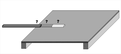
Now we have made a first sketch of the position of the sound bars, but we also have to decide on their length. Let’s have a short discussion on that point. If you have a wooden membrane or sound board and you want to strike that board with a sound bar running from outside and connected to that soundboard for a certain length. At what point would you like to end that sound bar? Halfway the membrane? Run all over? Up to 1/3 or 1/4 of the diameter of the sound board? Common sense is enough to understand that the optimum is not “all over” because it would hamper the flexibility of the board. It should be somewhere between 1/4 and 1/2. Fortunately it is not difficult to set up a small experiment to find out, that the best choice is about 1/4. This conclusion will be used in the decision on the length of the sound bars and referred to as the “1/4 principle”. Be aware that this “principle” only holds for the fundamental mode (0.0). For higher modes the optimal overlap will be shorter (frequency dependent).
Figure 17: The 1/4 principle
In the chapter on acoustic principles we described some main wood modes of the top. Now take a drawing of the design of your guitar top, including the provisional place of the sound bars and delineate the modes, that play a decisive role, especially the fundamental modes like (0.0), (1.0), (0.1), (1.2) and (2.0) as indicated in figure 18.
Figure 18: Main wood modes of the top
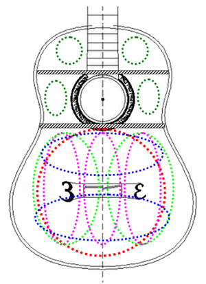
It is easy to see that some of these modes are almost free to move, where others will be hampered by the bridge or by sound bars. It is a challenge to find which sound bars will act as the main stirring mechanism of a particular mode or mini soundboard. If the answer is clear you can decide on the length, or at least the end point of that sound bar. The cross dipole (1.0) for instance may be hampered by the bridge, especially when the wings are long and stiff. Following the 1/4 principle you would end up with a bridge with a total length of ~ 9 cm. Applying the same reasoning for the tripole mode would favor a bridge with a length of about 18 cm. However for most frequencies a bridge without any wings may be the optimum (ref. 5). For that reason we prefer a bridge with a total length of 18 to 19 cm, a stiff middle part of 75 mm and wings that are adequately tapered towards the end.
See also the discussion on that subject in chapter 6.
Figure 19: Sound bar location for the EB-guitars
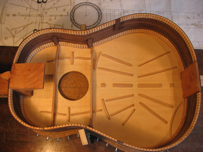
Do not worry about the fact that this first approach is not the unique outcome of a mathematical procedure. There is not such an outcome. It is one of the unsolved mysteries where we have to look for a practical solution, based on experience as well. One well-known luthier, who has designed a lot of guitars conform the Kasha design, stated quite honestly: “I use a lot of tapping, flexing, listening and just general intuition and fun to get the top to where I want it.” (ref 9 )
The “tap tone procedure”
Under “tap-tone-procedure” we understand construction adjustments to the thickness of the top or back and the associated construction and sound bars based on the tone (s) you can hear after tapping. It takes a little experience to find out how you can get the best (regarding volume and sound) tone out of a piece of wood by knocking on it. For a plate, half top, half back, top, back, side etc. in general you have to take firm hold of it between your thumb and forefinger. Then tap or knock forceful with thumb or finger of your other hand on the free hanging plate. Try out what the best place is for holding and tapping. Often you have to tap halfway the plate. Hold the plate close to your ear and listen carefully. In general you may hear one basic tone and sometimes several high tones (harmonics). If you remove material from the plate or from the bars the tap tone(s) will become lower. The goal of this procedure is to make the basic frequency louder, to improve the harmonics or to tune the tap tone of the back to that of the top during the construction.
It is important to realize that the tap tone of the top will change a lot after placing the sound bars and again after placing the bridge or after joining with the sides.
After the bars are glued to the top or the back there is another simple way to determine the natural frequency of the plate. If you have an electronic guitar tuner intended to attach to the head of a guitar, just clip it on the upper or waist transverse bar, knock and read the frequency from the dial plate.
Dome of the top
The top of your guitar may be flat or domed. The back is usually domed. To what extent the top or back should be arched is not the outcome of a mathematical procedure, but as usual, experience and application of physical principles will give us some guidelines on this issue. The advantage of a domed plate over a flat plate is an increased strength and resistance to deformations. The disadvantage is that the decreased flexibility will (frequency dependent) decrease the volume of specific pitches. This disadvantage applies especially for the fundamental mode (0.0). For high frequencies the volume will hardly be influenced by the curvature of the top. So if you want to favour the basses you have to limit the offset and choose for a dome that is just enough to prevent the top from indentation (dome ~ 2 mm). If you strive for more clarity in the high frequencies and a more even effect a dome of 6 to 8 mm is preferred.
Figure 20: Work board to dome the plates
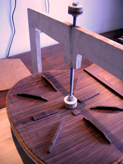
Experience has resulted in designs for classical guitars with an offset (maximum deviation from the flat plate) of 6 to 8 mm for the back and 2 to 3 mm for the top. The curve that the arched plate should follow is in most guitar construction books left to the reader. The usually given advice is to “slightly arch” the cross bars and arch the top or back by gluing it to these bars. Sometimes the arch is described as part of the contour of a circle or sphere with a specified radius. All these methods have the disadvantage to introduce unnatural strains in the top or back, that will result in energy losses in the vibrating plate.
In the box below you will find a short description of arching in a way the plates may choose their own “natural” curvature for a given maximum offset.
To dome the top (or back) the following steps are proposed (see figure 20):
- Prepare a work board (plywood) with the outer dimensions of your soundboard plus 10 mm at the outline
- Heighten the outer contour with the aid of cork up to ~8 mm
- Position the top on the work board and press the top down to the chosen offset with a stamp; this stamp should be positioned at the centre of the lower bout (equals the middle of the planned bridge)
- Measure the course of the offset all over the plate and make a map of it (compliance map)
- Remove the plate from the work board and fill the work plate with a cork plate (thickness again ~8 mm)
- Sand the cork plate so it duplicates the offset map
- Place the soundboard on the work board; put on the stamp and move it to the maximum possible depth (so the offset all over the soundboard reflects the compliance map)
- Place all important construction and sound bars at their planned positions and plane or sand them to the curve as given by the impressed soundboard
- Glue on all construction and sound bars
- Wait at least one week before you remove the soundboard from the work board
Dependent on the pattern of the construction and sound bars the offset of the plate will decrease as soon it is taken from the work board. For the EB-guitars, with their relatively flexible tops the offset decreases from 7 to 4 mm. So finally, dependent on the flexibility of your top, for a dome of 2 mm you have to choose an offset of your work board of 3 to 4 mm. For a dome of the back of 5 mm you have to take, again dependent on the flexibility of the board, an offset of 7 to 9 mm.
Thickness of the top
The thickness of tops of classical guitars varies a lot. First of all it depends on the choice of wood. Red cedar asks for a thickness of 1.5 to 2.0 mm. Spruce is often the first choice because of its acoustic properties and because it can be thinned to 1 to 1.5 mm and, if adequately braced, still keeps enough stiffness and strength.
The strength of the top is a combination of top wood, construction bars and sound bars, but far from just “adding” those three. In the case of construction bars, glued underneath the top, with the grain perpendicular to the grain of the top wood (cross bars), extra protection to cracks along the longitudinal axis is provided. The same holds for sound bars, that runs more or less perpendicular to the top wood fibers. Construction bars parallel to the plate fibers is another story. If you may choose between a normal plate with an extra bar or the same plate locally extra thick (resulting in the same overall strength) you should choose for the last option. Fortunately such a choice has hardly to be made. Only in the upper part of the guitar body it is interesting to have a relatively thick top.
Now let’s have some thoughts on variation of the top blade thickness. Imagine that you start with a thickness all over the top of 2 mm. Thinking of the main wave resonances it looks favorable to make the top flexible at places where it has to “flex” the most. From that viewpoint the top should be thinned as follows:
- Around the contour and in the vicinity of the waist bar (wave modes (0.0), (1.0) and (0.1))
- Along the midline/seam (wave modes (1.0), (1.1) and (1.2))
- Along the bridge (wave modes (0.1), (0.2), (1.1) and (1.2))
In view of the strength of the top around the sound hole an extra thickness of 0.2 to 0.4 mm may be an alternative to the usual construction in the form of a square or circle strengthening. Taking into account the wish to have extra support perpendicular to the grain of the top you should look for strengthening of the sound hole region especially in that direction and to choose a thickness in that region that is enough to compensate for the loss of strength. These ideas are in line with having a local mini soundboard in that region with a resonance frequency of ~7000 Hz.
Final construction
Now your first concept of the top is ready, it is time for “fine tuning”. There is still some elbowroom. Strength can be obtained by more thickness of the top, higher construction- or sound bars or less spaced sound bars. To gain insight in these possibilities it is good to make some simple comparisons.
Take for example the situation of sound bars of the same material as the top, with a height of 3 times the top thickness, running parallel to the grain of the top and spaced 20 mm of each other. In that case the resistance against bowing parallel to the grain is equally shared between the top itself and the sound bars. Decreasing the top thickness with 10 % from 2 mm to 1.8 mm can be compensated by increasing the height of the sound bars from 6 to about 7 mm. In the situation that the sound bars as described in this example make an angle of 45 ° or 90 ° with the grain direction of the top the necessary increase of height is of course even less, because the strength of the top is less perpendicular to the grain. Variations like these have to be within certain limits. As you know the positions of the sound bars were already fixed. The thickness of the top should be chosen within the lines described in the foregoing paragraph. Variations in thickness should be gradual. Variations in thickness means cutting through the wood fibers and that is something you want to avoid if possible.
Going through examples and simple calculations like these you will find that the changes within these constraints are small. Important is that the choice between stronger bars or a thicker top is dependent on the exact location at the top you talk about. In regions of mini soundboards meant to resonate at a high pitch you can afford to allow a thicker top and a corresponding decrease in bar enforcement.
9 The back
As in the case of the soundboard let’s first think about the acoustical function of the back. In The brigde we argued that the whole guitar box should be as rigid as can be with an exception for the top and the back in its function to support the main air modes. So we have to know which parts of the back contribute to those modes. In this respect it is sufficient to distinct just two parts: the upper and the lower bout.

From experiments on “standard backs”, e.g. of normal size and usual bars we can conclude that it is only the lower part of the back that moves and contributes to the air modes (0.0), (0.1) and (0.2). The main reason of course is that the upper part of the back is stiffened anyway by the inevitable connection with foot and heel. Now, as in other construction parts of the guitar, it is of no use to have energy absorption in parts with a minor or no contribution to the sound production. Therefore the best solution is found in a back, which is rigid in the upper part and is flexible in the lower part. This starting point should be followed without compromise and can be worked out in the same way we did for the soundboard.
The lower part of the back is bordered by a cross bar, which location is chosen in the same way as the waist bar of the top. It will be positioned right under the waist bar. As far as the flexibility of the back is concerned, especially the (0.0) and (0.1) modes we like to back up. Do not think in terms of sound bars that distribute sound waves in the wooden back or should divide the back into “mini backs”. The task of the back is only to reinforce the guitar box and to show flexibility needed for optimization of the (0.0) and (0.1) modes. That goal has to be reached by a combination of plate thickness and construction bars. The argument to use construction bars as well is based upon the fact that the strength of a piece of wood is much (order of ten) higher in the grain direction than perpendicular to that direction. The different viewpoints, mentioned above, lead to a strengthening of the back by a star pattern with its centre in the middle of the lower part of the back. It looks a little bit like the X-pattern of the steel string guitars but with the “X” centered in the lower back. What we strive for is a strengthening that is rather homogeneously divided and therefore we have to use more radians and have to decrease the radians in the centre. If we want to have a symmetric pattern (and the air modes are symmetric) we end up with a star with 8 radians. It will be clear that such a pattern will stiffen the centre of the belly unnecessary and therefore we will let the radian’s end at a certain distance from the centre and from the boundary. This “X” pattern is also quite suitable in fixating the tail block with regard to the neck.
Figure 21: Bar pattern for the back

A second modification of the star pattern is based on the view that the strengthening should be focused in the direction perpendicular to the grain of the back. So the radians crossing the grains should be located closer to each other. I don’t think, if possible at all, that there is an algorithm available that gives you an exact solution for the position of the radians in this way. There are too many variables involved. But the optimum solution should show the appearance shown in figure 21.
In that pattern all radians end at a distance of the centre of 5 cm from the centre and 4 cm from the boundary. The sideward pointing radians make an angle of ~30 ° with the cross bar. For arching the back see the discussion in chapter 8 (dome of the top).
10 The sides
From the discussion on the design of the top and the back the following starting points for the sides can be derived:
- In the upper part the side should be rigid, giving no allowance to movement in any direction and an inflexible connection to the back
- In the lower part the side itself should be rigid too, but the connection with the top and to a lesser extent with the back should be flexible in a sense that the edge is allowed to twist
For the construction of the guitar the pre-cut sides have to be bowed with the aid of an iron steam pipe or the use of a bending mould after pre heating the sides. In order to facilitate the bending process the sides have to be thinned before bending, to a thickness of not more than 2 to 3 mm, depending on the wood and may be on the skill of the builder. So for a rose wood side a third starting point is an overall thickness of less than 2.5 mm. Because we see the sides as a rigid part of the frame construction we could decide to stick to that 2.5 mm thickness, with exception for the vicinity of the glue edge of the lower bout and lower part of the back.

But again, as was the case with the top and the back, we will improve the strength if we add some reinforcement bars, perpendicular to the grain of the sides, allowing for an extra thinning of the side in that region. The positions for those bars are indicated where the sides are extra vulnerable, e.g. the places which maximum curve and strain. To reflect the starting point of a flexible connection to the top these bars will not be connected to the top but have a length of 7 to 8 cm. Finally the thickness should be around 2 mm. For high quality rosewood even less, but not less than 1.5 mm.
The tail block
From the foregoing discussions on the top, back and sides the starting points for the tail block are more or less obvious:
- Start with a rigid piece of wood, strong enough to act as an inflexible, unmovable connection between the two sides.
- Bevel the tail block to the width of the linings to free the top as much as possible
- Do the same for the back side
- The grain of the tail block may be parallel or perpendicular to the grain of the sides. Most in use and satisfying is to have the grain horizontally, so parallel with the soundboard and back. A good alternative is to have the grain of the endblock vertically and use an epoxy as glue.
Another approach is to make the tail block out of two pieces of wood (with their grain perpendicular to each other) glued together.
11 Miscellaneous
Decorations
Final construction adjustement
Connections and glues
What we ask from connections between different parts of the guitar are the following characteristics, in order of importance:
- The connection is at least as strong as the different parts
- Zero loss of energy
- Ample hardening time
- Crack-filling properties
- Transparency
Many guitar builders use, like their colleagues in the past, bone glue to reach these goals. However it is questionable whether nowadays this is (still) the best choice. Why should we use all kind of modern tools and construction methods and still stick to glue that was used centuries ago? An argument that is commonly used to defend that choice is the possibility to unfix the connection when needed does not sound as an advertising seller. Maybe with violins it is a different case but most parts of the classical guitar will never need to be repaired and construction and sound bars can be reached, replaced or repaired via the sound hole. These considerations may give rise to the choice of a sound hole that permits accessibility by hand. In the case your hands are exceptional large you have to consider not to do the repair work yourself. But of course the best idea is to construct your guitar and use glues in such a way that repair will never be needed.
Many guitar builders now recommend the use of resin glues as “Titebond” or even stronger epoxy glues (see e.g. ref.22 ).
An important issue in choosing adequate glue is the question, whether the two surfaces can stick together perfectly. For many parts of the guitar that we have to glue together the surfaces will not join closely and small gaps will stay, especially when the different parts are relatively stiff. In that case crack-filling properties are a must. For that reason and in view of its strength I use almost exclusively slow drying two component epoxy glue.
Decorations
In the Renaissance as well in the Baroque time string instruments were often used as a gift to a beloved or dreaded person. Gifts that reflected the admiration or devotion to the king, princess or whatsoever. That resulted in the situation that many instruments of that time, in our eyes, were overloaded with all kind of decorations. Different precious materials, like tropical hard woods, tortoise, abalone, ivory et cetera were ingenuously shaped and used in almost all parts of the instrument. Nowadays, at least for the classical guitar, less labor-intensive and less abundant decoration is preferred. Still it is worthwhile to give ample attention to the choice of materials, finish and decoration. Ultimately, we want to have a guitar that is gorgeous to listen to but also outrageous to look at!
Most important in this respect are the choice of wood and the finishing of it in the final stage of the construction. The material choice (including color and pattern) of the sides, back, top, neck, head, fret board and bridge should be compatible and their color and appearance should harmonize. It is better to stick to a limited number of wood species and materials. As a rule of thumb back, sides and head veneer are the same. The bridge may also follow that choice, as long as these parts are made of a relatively hard and strong wood.
How nice extra decoration may be, it never should have any negative effect on the acoustic quality or playability. From that point of view there is hardly room for any decoration on the bridge or on the top with an exception for the outline of the sound hole, where a specific “personal” rosette is quite usual.

Decorations that do not contribute to the strength or durability of the guitar are only allowed on those parts that should be completely rigid. As such can be mentioned the neck and head, the upper part of the sides (region of the upper bout) and the fret board as long as the playability is not affected.
Figure 22: Personal label

As a form of “decoration” many guitar builders add a “personal touch” like the form of sculpture on top of the head. Also, nearly every guitar builder has a personal label, that is attached to the inside of the back, and is visible through the sound hole.
There are many ways to give your guitar such a personal touch and the best advice I can give you is: think about it, take your time and give it all the effort it asks for. It will pay off!
Final construction adjustments
The different physical phenomena, influenced by materials, dimensions and construction are that complex that it is impossible for a given design to forecast exactly what the sound of that guitar will be. Not exactly but to a certain level of confidence we are able to construct a guitar which fulfills the wishes we have on the 5 main construcction principles as described in the introduction. Still, it is wise to use the available possibilities to adjust the instrument to our special wishes during the construction as far as possible:
- Follow the “tap tone procedure”during the construction of the top and of the back.
- If you have the time, guts and the necessary tools, measure the deflection of the top and the back after completion (how to do it and which adjustments may be used is described in ref 15 ).
- In the situation, that you have domed the top and decided upon the dimensions of the bridge and saddle you can select the body-neck angle to end up with an appropriate fret board. Less adequate but possible is to adjust the height of the saddle at the end of the construction (see chapter 5 ).
- Sometimes the finger board is glued to the neck before fretting, sometimes afterwards. If you do it before, it gives you the opportunity for final adjustment (thinning) of the fingerboard in view of the action of the strings and the height of the saddle (see chapter 5 ). However, fretting the fingerboard before it is glued to the neck is an easier and safer job.
- Polishing the top can be done before or after installing the bridge. Gluing the bridge afterwards has the advantage that polishing of the soundboard is easier and the result may look better. However, if you leave polishing to the very end (after you have installed the bridge) you can string it up, listen to the sound and make final adjustments to the thickness of the soundboard and the sound bars. Especially local thinning when the sound of the basses is too weak. This last improvement is so important that my advice is to install the bridge before the final polishing.
In case you wish to thin or enlarge the weight of specific bars (after or before complete finishing and tuning) the opening of the sound hole should be wide enough to do so. So the sound hole should be large enough for your hands to make those final adjustments possible.
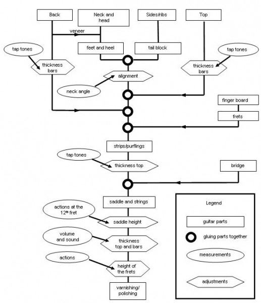
In the flow diagram as given in figure 23 below these possible adjustments are indicated.
Figure 23: Guitar construction and adjustments

12 References
| 1 | Rossing, Thomas. D An Introduction to Guitar Acoustics GALQ Volume 11, #4 1983 and Volume 12, #1, 1984 |
| 2 | Rossing, Thomas. D Sound Radiation from Guitars American Lutherie #16, 1988 |
| 3 | Caldersmith, Graham Radiation from Lower Guitar Modes American Lutherie #2, 1985 |
| 4 | Caldersmith, Graham Dissolving the mysteries GALQ Volume 10, #4, 1982 |
| 5 | Jansson, Erik V and Meyer, Jürgen Function, Construction and Quality of the Guitar edited by Erik V Jansson Publications issued by the Royal Swedish Academy of Music. No.38 1983 |
| 6 | Somogyi, Erwin Principles of Guitar Dynamics and Design American Lutherie, #36, winter 1993 |
| 7 | Beyers, Greg Classic Guitar Intonation GALQ Workshop 1995 |
| 8 | Wyszkowski, Paul Soundboard Bracing Considerations GAL Data Sheet # 171, 1981 |
| 9 | Eban, Gila Kasha Guitar Soundboard GAL Data Sheet # 243, 1983 |
| 10 | Eban, Gila Kasha Soundboard without Waist Bar American Lutherie #8, 1986 |
| 11 | Romanillos, J.L. Antonio de Torres (Guitar maker His life and work) Winspear, 1995 |
| 12 | Eendebak, Bert De vorm van een klassieke gitaar De bouwbrief 13/01, August 2008 (page 5, 6 and 7) |
| 13 | Verbeij, Oswald. J Fingerboard Relief A theoretical exploration (private communication, 2008) |
| 14 | Davis, Ted Evolving the classic Guitar Soundboard Gal Data Sheets # 238, 1983 and #294, 1984 |
| 15 | David C. Hurd Left Brain Lutherie Ukuleles by Kawika, Inc. ISBN 0-9760833-0-4 |
| 16 | Sloane, Irving Classic guitar Construction Diagrams, photographs and step-by-step instructions New York, 1966 |
| 17 | Etienne, Wil Gitaarbouwhandleiding 1984 Printshop Wijchen, Heilige Stoel |
| 18 | Brosnac, Donald Ich baue mir eine gitarre Karthause Verlag G.m.b.H., 1984 ISBN 978-3-92210-05-8 |
| 19 | Middleton, Rik The Guitar Maker’s Workshop ISBN-13 9981861260407 Crowood, 2004 |
| 20 | Cumpiano, William R. and Natelson, Jonathan D. Guitar making Chronical Books L.a.c. 1993 ISBN 10: 0-8118-0640-5 ISBN 13: 978-0-8118-0640-4 |
| 21 | Courtnall, Roy Making Master Guitars 1993 Robert Hale London ISBN 978 0 7090 4809 1 |
| 22 | Jacobson, Paul Epoxy GAL Data Sheet # 90, 1978 ISBN-13 978-0-8118-0640-4 |
http://www.designofaclassicalguitar.com




Great and a very useful article! I looked for something like your diagram “Sound level as a function of the height of the saddle” but rest of info just superb.
Thanks for information
Why have the small bout at the fingerboard end of the guitar? If instead you have the large bout next to the fingerboard then the guitar supports itself on the left thigh without the need for any other support and is very comfortable.
you are a genius..
Subject: Question on “Position of neck and guitar body”
Hi Bert,
I don’t understand clearly what you mean by “dome (maximum height of the top above the edge.”
Does “the top” mean the highest point of the sound (front) board around the bridge, as the area around it is slightly raised?
Does “the edge” mean the edge around the periphery of the sound board?
Best Regards,
Ken
You mention issue with tops cracking beside the bridge. Would this not be a good reason to use a bridge patch? The hardwood bridge glued with the grain at 90 degrees to the top generates a stress area at it’s ends due to the uneven forces. The bridge patch creates a 3 ply layer that is more balanced and if it is run past the bridge ends supports that area where it is most likely to crack. An alternative might be 2 small patch’s just over the ends of the bridge, rather than one continuous one.
This blog was… how do you say it? Relevant!! Finally I’ve found something which helped me. Appreciate it!