-The peg box
The material for the peg box and the pattern. The wood is 7mm thick, but will be planed down to 5mm after assembly.
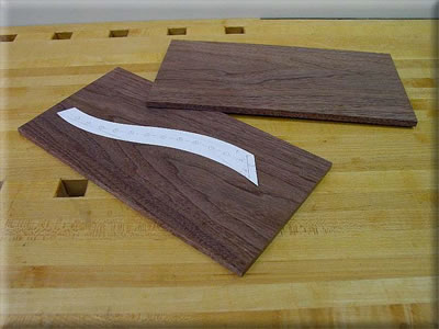
The negative pattern is used in order to see the grain of the wood and orient the peg box walls accordingly.
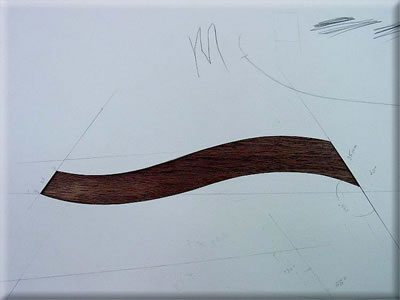
The peg box assembled. The end pieces are described below.
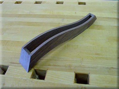
The peg box tapers from the neck end to the tip, so the blocks at either end must be tapered as well. The angle of the edges of the blocks is about 1.5 degrees. I used a little angled fence and some sandpaper to establish the angle. The thickness of the pieces is about 7mm.
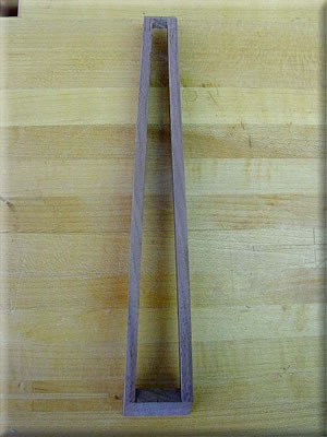
The peg box also tapers from top to bottom. That means the sides of the blocks must taper as well. I planed this angle by hand before I sanded to the other angle.
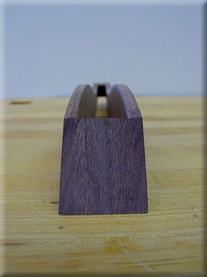
The block at the neck end of the peg box is left long and trimmed flush after gluing when the edges of the box are sanded flat. The thickness of the walls is about 5mm. Hankey’s book was a bit unclear about this, so I used my Turkish oud as a reference point.
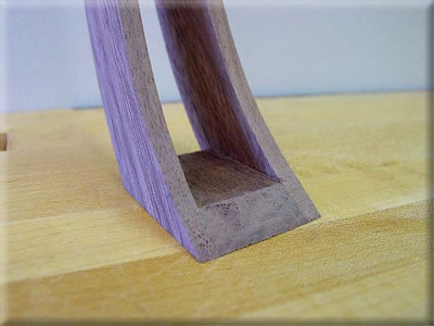
The top corners are rounded over to allow for string clearance.
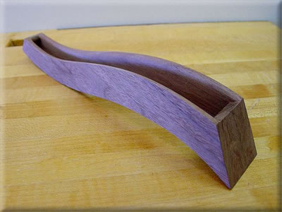
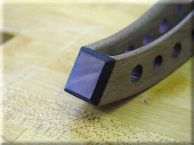
The tip of the peg box. Later this end will be covered by a decorative piece, scrollwork, piece of bone, etc. I have not decided which.
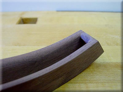
The back of the pegbox is covered with a thin (2mm) piece of wood. It is bent to shape like the ribs and glued on. In order to have an easy and successful glue up, I built a dedicated jig for this task. First I bent the bottom so it fit well with just hand pressure. I made sure it fit without any gaps. Next I cut it a bit oversize on the sides and left the ends long. To make the jig I first cut a wide block of softwood to the taper of the peg box. Then I laid the box on the block and traced along each side. I then bandsawed the material between these lines. I added a strip of cork to distribute the clamping pressure. At the neck end, the joint didn’t quite close up enough so I cut some quick wedges and pushed them in to close the joint. After the glue cures the bottom will be planed flush to the box.
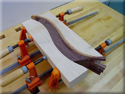
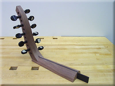
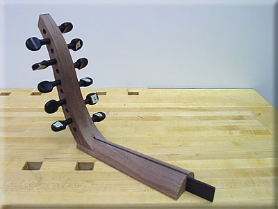
The box bottom trimmed flush and the peg holes drilled and reamed.
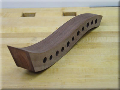
The finished peg box (minus decorative cap at tip). The pegs are a little shorter than what I wanted, but for a first try I am satisfied. Fitting the pegs must be done with great attention and patience. Reaming a bit at a time and sanding the shank very sparingly is the best way to keep the shanks long.
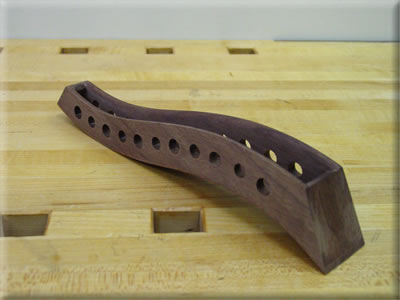
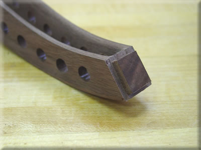
I glued a piece of figured walnut to the tip of the peg box, then I rabbeted all around (about 3mm) for Blackwood strips that will be glued in.
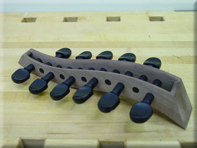
The tip of the pegbox with the inlaid Blackwood banding. The job could have been a bit neater.
This ends the peg box section.
-Neck
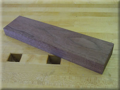
The blank for the neck. It is tapered in thickness from the body to the pegbox.
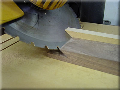
I did the straight cut for the peg box notch on the table saw. I used a radial-arm saw for the angled cut, then cleaned the corner out with a fine saw and chisel.
The finished notch for the peg box. The notch is cut before shaping the neck to make the joinery easier.
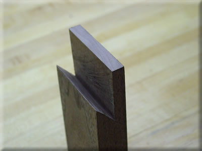
Here I am testing the fit of the peg box in the neck. The back of the peg box is a bit curved, so I filed the angled side of the notch to match as close as possible the back of the peg box. It only needs to fit at the middle because the sides of the neck will be tapered down.
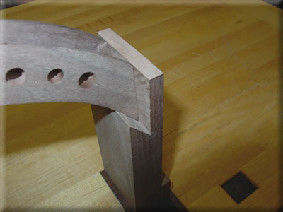
The neck end of the back planed flush. The ribs are a bit too thick. In order for the neck to meet up with the back, the ribs must be trimmed to the correct size. After I join the neck to the back and shape it, I will transfer its outline to the back and trim the ribs to match the shape of the neck.
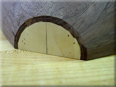
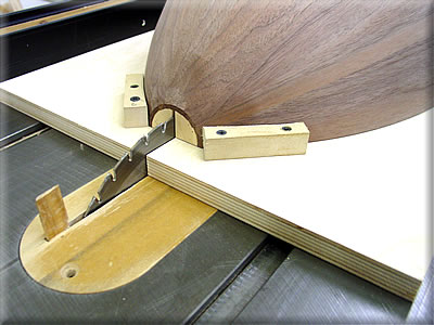
The jig I made to cut the slot in the neck block. The neck is made in such a way that a thin (3mm) piece of wood runs from the pegbox, down the entire length of the neck and into the neck block of the body. This is a very strong method of construction. Hankey says to use a saw. I decided to use my table saw. I’m not too bad with hand tools, but I like to be precise as possible. Sometimes this means using hand tools, sometimes power tools. In this case, the table saw yields quicker, better results.
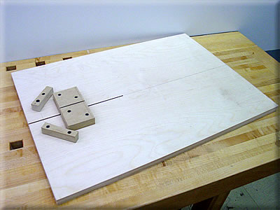
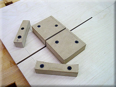
In order for the jig to work precisely and safely (reducing risk of injury to operator, and almost as important in this case, the valuable oud back!) the back must be held in position in all planes. These blocks keep the back from sliding forwards, backwards or laterally and my hand keeps the back from raising up. I cut the smaller blocks to match the curve of the back. The larger block rests against the back of the neck block. The back fits snug into the blocks.
I struck a line parallel to the fence side of the jig and dead center down the middle. The tail end is not held with any blocks.
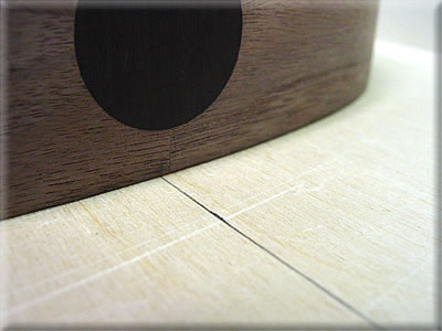
The jig on the table saw after the cut. It slides against the fence.
The result of the jig. A perfectly aligned 3mm slot. I built the jig and cut the slot in the neck end in about 10 minutes, and the slot is right where it is supposed to be and smooth and uniform in width. This would have required much more time and effort to do with a handsaw, files, sanding sticks, etc, and the results would have been much less precise, at least by my hands. Now I must figure out how to cut with the same precision the bottom end of the pegbox, which receives the same slot.
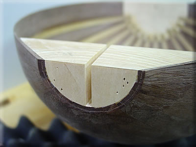
The stringer is African Blackwood. It is a very stiff wood, but not as hard as ebony. It is very good to work with. I am using this wood for several parts of the oud. The fit is just snug.
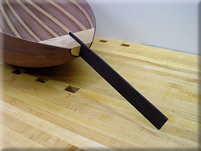
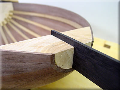
The neck cut down the center with edges jointed
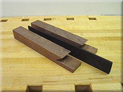
Another example of the utility of power tools. I modified the neck block slotting jig for the peg box. The three blocks hold the neck end of the peg box secure and properly aligned while cutting the slot.
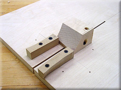
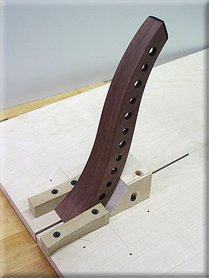
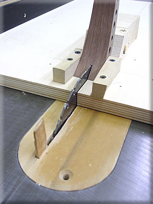
The slot is exactly where it should be and is the correct width.
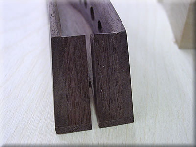
Here I am testing the fit of the neck, peg box and stringer. I made a small mistake and cut the slot for the stringer in the peg box a little too deep, forgetting that I will be removing a couple millimeters from the neck thickness when I shape it after it is glued. So there will be a gap between the top of the finished neck and the end of the slot in the back of the pegbox. I will have to cut a patch to hide this small mistake. If I do a good job, it should be invisible.
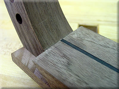
The stringer fits very well.
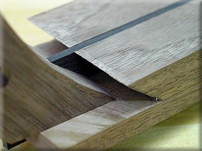
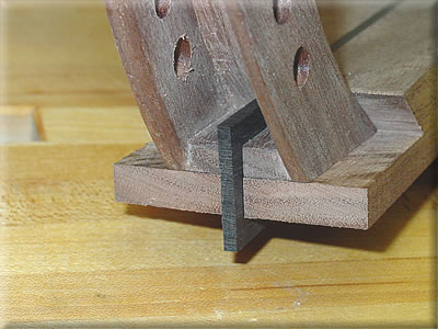
From the photo it is evident that this joint is not going to come apart anytime soon. As an experienced woodworker, I have to say that this is an excellent method for joining the peg box, neck and back. Nice engineering, Mr. Hankey.
The neck after shaping. I used a carving chisel to take off the corners to within 3mm of the line I drew to establish the contour. Then a block plane to get very close to the line. Finally, some sandpaper and a cork pad to smooth it. For the neck, I find that a piece of 6mm (1/4″) thick cork makes a better sanding pad than foam or sponge. It is flexible enough to eliminate flat spots, yet stiff enough to ride over the sharp edges of the peg box and body joints, and not round them over. I noticed that the neck on some ouds tapers in width, but not so much in thickness, so the bulkiness towards the neck end is eliminated. The measurements on mine are 19mm thick at the pegbox, and 26mm at the body. This feels a bit thick and could have been thinner, but I have seen other ouds like this too. I don’t think the strength of this joint is compromised by having the neck thinner (although a thicker neck certainly does make it stronger), since the stringer is responsible for the majority of the neck’s connection to the body. This detail is easy to overlook because the thickness of the neck at the body must be established when the neck block is carved–virtually the first step in building the oud
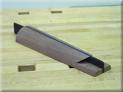
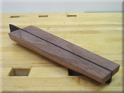
The peg box in place to check its relationship with the neck.
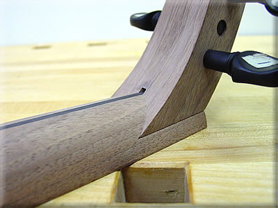
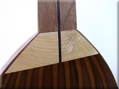
Close up of the pegbox/neck joint. The mistake is visible just above the blackwood stringer. A jewelry maker I know suggested I fill the void with blackwood instead of walnut. He has good experience with these sort of “happy accidents”. That way it will appear as an intentional design detail, instead of a mistake. If I use walnut, there is a pretty good chance that it will be noticeable. Otherwise, the fit of the pegbox is satisfactory.
The ends of the ribs are a bit thick and need to be trimmed to match the neck.
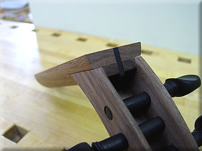
The trimmed rib ends. I could have spent a lot of time and made this match very closely, but I will be gluing on a little “bracelet” of veneer to cover the joint. I prefer the look of this anyway, regardless if the neck fits perfectly or not.
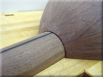
The neck and body joint from the front. When I glued the neck together, it slipped ever so slightly along its length, so one side was a bit “longer” (about the thickness of a sheet of paper) than the other. It took a fair amount of fitting to get the neck to sit flat against the neck block, especially since the stringer gets in the way during the process.
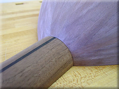
Testing the fit of the neck and pegbox.
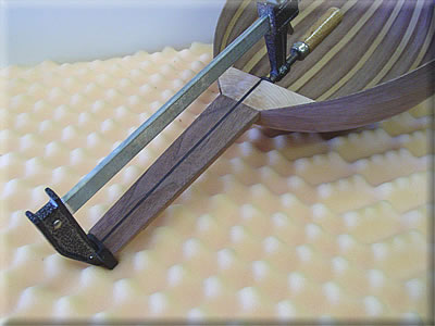
Gluing the neck to the body after many test fittings and checks
After gluing the neck to the body, the alignment was good, just about 1mm below the neck block at the nut end. However, after placing the back in the straightening jig, it seems the tail block was raised a bit in the process. Consequently, the neck is now “out of alignment”. I have yet to determine a fix for this.
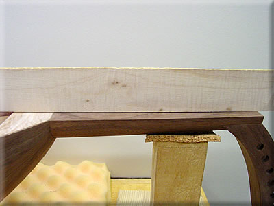
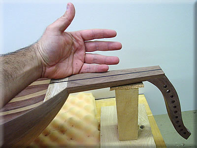
Here is a picture of the neck with my hand for size comparison. This ends the Neck construction.
-Soundboard
The two halves of the soundboard are jointed along one edge and joined with a joining fixture. It is simply two pins (screws) on each side of the halves, attached to a flat board. They are placed a bit narrower than the width of both halves, so they are raised slightly in the middle. To clamp the joint, simply push down at the joint and place a heavy object until the glue cures. I also placed a strip of newsprint under the seam to prevent the boards from adhering to the fixture. Waxed paper should work too but I have read that it inhibits the glue drying process.
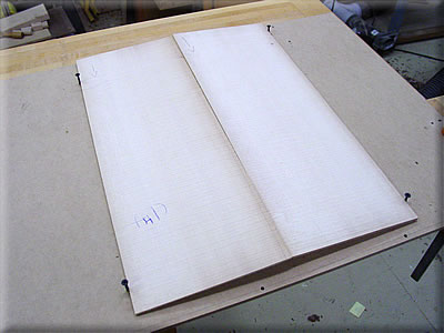
The joined soundboard. A friend with a drum sander took it down to just under 3mm for me. The rest will be done by hand.
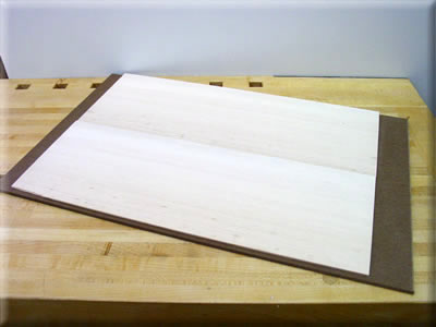
A close view of the grain. It is not the prettiest piece, but the tone it produced when tapped was the best of the samples I had, so I used it. The wood is Livane Spruce, from Turkey. I will add further opinions of the wood as the oud construction continues.
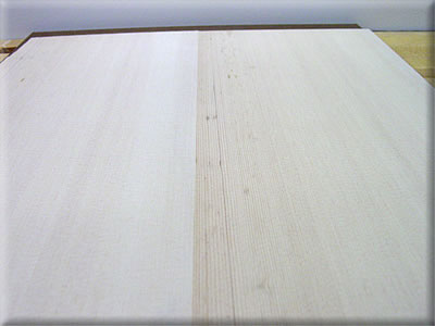
The center of the soundboard. After much research, I decided not to bookmatch the top, for various reasons. Oud luthiers use both bookmatching and slipmatching. Both apparently have their advantages. On that note, I decided to end the research after about four days and get on with the construction. The grain lines are nicely quartersawn and fairly tight. The stiffness of the top is fairly uniform across its width, despite the variable grain line spacing.
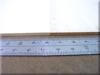
The left side (looking towards the neck)
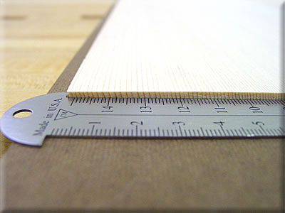
The right side.
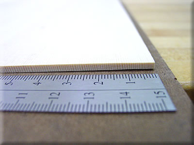
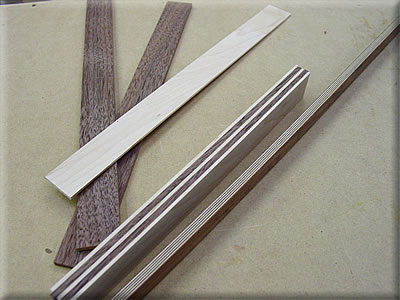
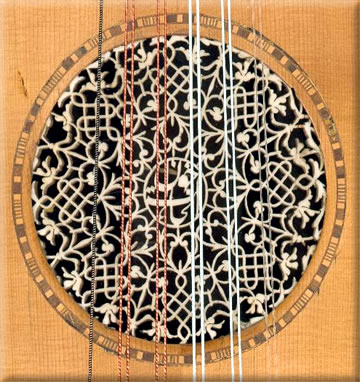
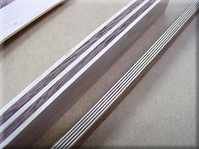
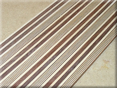
The rosette around the soundhole is made up of small tiles of walnut and maple. I glued up different thicknesses of walnut and maple as well as veneer in order to copy a pattern found on a 1908 Roufan Nahat oud. See below for an image of this pattern
The 1908 Nahat oud with the tile detail.
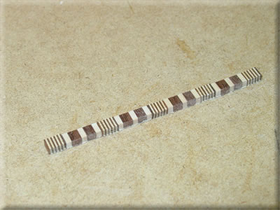
A closer view of the tile blanks.
The blanks sawn into 3mm thick slices. I left them thick for easier handling. This amount should yield enough for several rosettes.
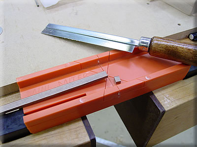
I picked up this Zona razor saw and miter box at the local hobby shop for only $7.50. It cuts on the pull stroke, has 32 tpi, cuts extremely smoothly and leaves no tearout or fuzz of any sort. It works very well for cutting the individual tiles.
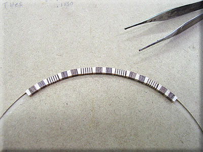
Here are some tiles laid out in order. These tile will also be used at the edge of thesoundboard after it is glued to the back.
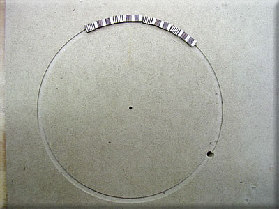
A quick mock-up of the rosette. The channel is a test cut in MDF with the laminate trimmer for proper diameter, which is 122mm on the inside of the rosette, which itself is 4mm wide. The tiles will have to be slightly sanded to the curve and angled a bit at the ends to fit properly. There will also be a line of walnut veneer on the inside and outside of the rosette to create a border.
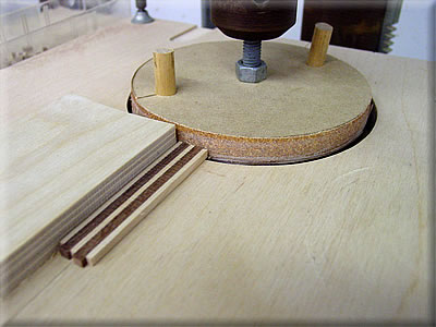
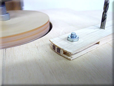
Here I am sanding the end of one of the slices. This surface is the inner edge of the rosette. (The sanding wheel is this diameter) The jig is from Cumpiano and Natelson’s book on guitar building, specifically, the section on inlaying an abalone rosette on a steel string guitar. My rosette is essentially the same, replacing the abalone sections for wood. I sand the end and cut off a tile, and repeat until I have about 20 tiles.
This is the second half of the jig which sands the outer radius of the tiles. It is just a little stick that holds the tile while it pivots at the correct point. This not only makes the outer curve on each piece, but also sands each tile to the same width. It is used for both the maple/walnut tiles and the veneer tiles.
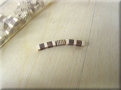
The tiles after sanding both curves.
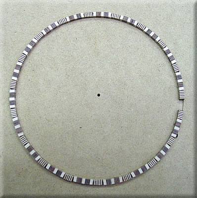
The larger tiles still need to have the ends tapered. The veneered tiles remain as they are, so as not to remove any of the detail.
The jig (shooting board) I made for tapering the curved tiles. The top block is a section of the inside diameter of the rosette. Since I only tapered the maple/walnut tiles, I cut the flat edge off center (narrower side) to compensate for this. If I were to taper all the tiles, I would have made the straight edge bisect the center point of the circle. The plane is a Lie-Nielsen Large Shoulder Plane. Lie-Nielsen makes the finest hand planes, and I am pleased to own two of them. The second one is the 164 Low Angle Smoothing Plane which I use quite extensively.
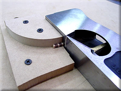
I hold the tile in place with my thumb while planing with the right hand.
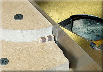
The maple pieces at the ends are planed until the taper goes across the entire tile end.
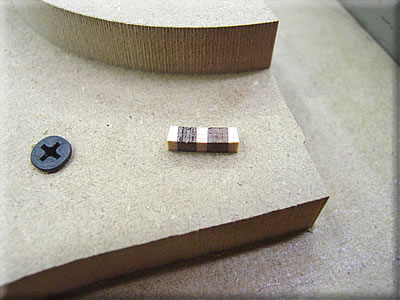
A test fit in the sample groove. The taper is correct. The tiles butt neatly against each other.
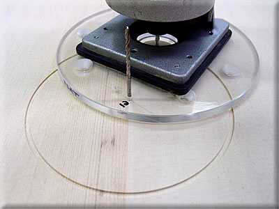
I made a test cut in some scrap wood to set the router to cut the correct inside diameter. I left the screw holes in the clear sub-base a bit large to allow for minute adjustments. When I got the correct diameter, I went ahead and cut the first groove in the soundboard, which I am doing here. I am using a solid carbide, 1/8″ (about 3mm) diameter spiral downcut bit. The spiral downcut shape of the bit keeps the edge very crisp and causes absolutely no fuzz or tearout, like a normal router bit might. I repeated these steps to cut the outside diameter. The channel is .127mm (.005″) wider than the tiles plus two lines of veneer to allow for glue space. This is a very minute amount, and was measured very carefully with a dial caliper. Needless to say, the tiles and veneer are accurately made to a tolerance of about a thousandth of an inch. The depth of the groove is just over 1mm. Hankey’s book says to make it 1.5mm, and then sand the back to 1.5mm thick. This means that the rosette is attached to the soundboard only on its edges! However, when the rose is attached later, this becomes reinforced by the edge of the rose being glued to the back of the soundboard. Nevertheless, I opted to leave the channel a bit shallow to keep the top intact. The top is fragile enough as it is.
Test fitting the tiles and veneer lines in the finished channel.
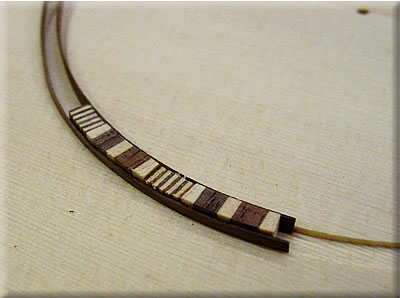
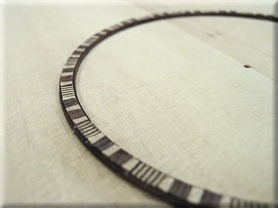
The finished rosette glued in the channel. I used PVA (white) glue for its longer open time. I began by covering the bottom of the channel with glue about 5cm at a time. Other than the first tile, I didn’t bother gluing the contact surfaces of the tiles. As they are pressed in place, the excess glue is squeezed out and takes care of these joints. I laid in the first tile with the veneer and pressed down, laying in alternating tiles and spreading more glue as necessary. The veneer has a tendency to raise up, so I made sure I pressed it down at each tile insertion. I have yet to see whether I was judicious enough in this after I plane down the tiles to the surface of the soundboard and reveal any mistakes.
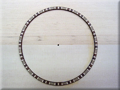
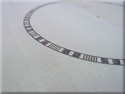
The rosette after planing it flush.
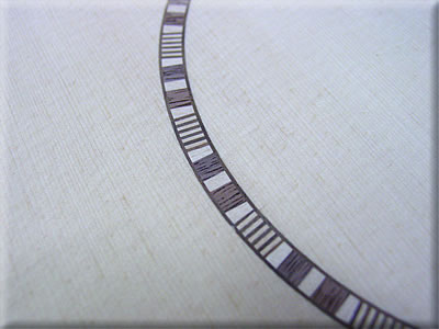
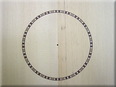
The completed rosette.
-Soundboard 2
The blank for the bridge of African Blackwood.

The rabbet is cut on the router table. Fence design is by routing expert Pat Warner.

Detail of the routing.
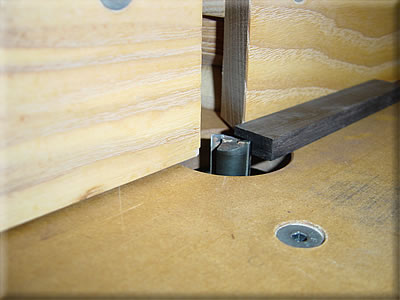
The rabbet cut into the bridge.

The ends of the bridge cut to shape and the ends of the tie block shaped to a half-circle.

I decided to copy the tile work of the rosette here. I routed out about 2mm deep for the inlay.

A better shot of the notch for the tiles
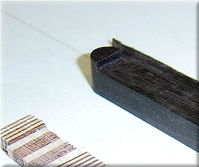
The completed bridge.


After the rosette is inlaid, the soundboard is taken to final thickness. I tried for 1.5mm. My friend with the thickness sander was out of the shop today, so I decided to plane it to thickness. Hankey’s book stresses not to use a plane, but instead sand. Sanding is not one of my favorite activities. I have confidence in my planing abilities, and in my plane. It is a pre-WWII Stanley #7 jointer plane. I sharpened the iron until I could easily shave with it and built a special work board to hold the soundboard while I planed. It is simply a flat piece of MDF with three very thin (1.5mm) pieces of maple superglued to the MDF for the stops. They are actually leftovers from the rosette tile blanks. The heft of the plane and long nose section keep the soundboard from flexing while planing. Even with this special setup and plane, it is important to cut directly across the grain with the plane skewed about 20 degrees. Planing with the grain is far too risky in this situation. I got continuous cross-grain shavings. About 8 passes and I was very near thickness. I then sanded the back with 100 grit until all the cross grain plane marks were gone. The front was then sanded to 220.

The next thing I did was cut out the soundhole. I used the same setup as for cutting the rosette channel.


Tracing the outline in order to cut the soundboard to shape.

I cut about 4mm away from the line with a stout and sharp knife, taking repetitive light cuts until I was through. It is important to cut with the grain.

The soundboard cut to rough shape.

I couldn’t resist laying the soundboard on the back in order to sample the look. It is really starting to shape up. I only left the soundboard on the back for a moment to photograph it. It is only supported at the edges. One false move and the fragile soundboard could be broken very easily.

A piece of bone I picked up at the local pet store. I sliced off a piece on the bandsaw for a round inlay at the center of the shams (rose). I may also use this for the nut.
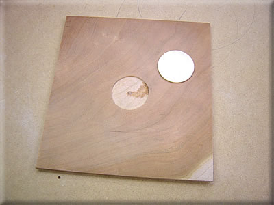
The blank for the shams (rose) of cherry with the recess and the bone inlay.
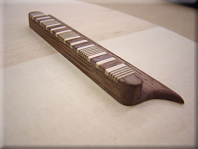
I decided not to use the Blackwood bridge I made earlier. I was told by an oud historian that dense woods such as Blackwood, Ebony, Rosewood, etc. are not really used on ouds. I suppose the density of the Blackwood absorbs more sound than it transmits to the soundboard. Either way, I plan to glue the bridge with hide glue so it can be removed and replaced if need be in the future. The walnut bridge was made the exact same way as the Blackwood one.
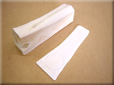
Wood for the “raqma” (pickguard). The veneer was made from some resawn cherry I had. The original piece was 3mm thick. I double-stick taped the ends to a thick piece of plywood and ran it through a thickness sander until it was about .7mm (1/32″) standard veneer thickness. I chose to do this rather than buy veneer because I liked the figure of this cherry, and it didn’t cost any extra.

Design for the shams (rose). I divided the circle into 8 sections. Each section is a mirror image down the center, so I only had to draw one sixteenth of the pattern. The pattern was scanned into the computer and repeated to form the circle. The middle is an Arabic calligraphic monogram of the name “Khalaf Brothers” or “Ikhwan Khalaf”. The name Khalaf is my real family name. Many thanks to the following gentlemen for help in designing the calligraphy (my own Arabic writing skills are almost non-existent): Nazih Ghadban (Lebanese oud maker-see homepage), Wael Kakish (www.kanzaman.org), and Mike Malek.

Cutting the design. A previous attempt using the cherry/bone blank was unsuccessful. This is a thinner (2mm) piece of laminated birch. Using a laminated blank assures that there are no cross-grain sections that break off easily. The wood is cut using a jeweler’s saw and a very fine blade. Cutting the design is more difficult than I imagined, and more time consuming. This amount took about two hours.


The finished rose prior to some final touch ups.

The bridge in preparation for gluing. It’s taped in position and a special caul is made to press on both surfaces while clamping.

A thick caul is used under the top.

Clamping the bridge. I used hot hide glue. The stuff is reversible and stronger than conventional yellow glue. It is also difficult to work with. It sets up very quickly, and I mean in less than a minute. I guess I will see if I did a good job or not when I string the oud and the bridge stays put!

The “raqma” pickguard.

To glue the pickguard on, the sound board needs to be supported from underneath. I curved these blocks so I wouldn’t pop the glue joint on the braces and put a layer of cork for extra support.

The pickguard outline is traced on a piece of paper and cut out. I positioned the pickguard in its location (with a bit of masking tape on the back) on the soundboard and taped the paper with the cut out in position around it.

I removed the pickguard to reveal the gluing area. I applied hot hide glue to this area.

I also applied some glue to the back of the pickguard. I layed the pickguard on the iron for a few seconds to warm it before applying the glue. By the time this was done the glue was beginning to gel. No problem, though. It was tacky. I positioned the pickguard and pressed down enough for it to stick. I then briefly passed the hot iron over it to re-warm the glue. The pickguard slid a bit when the glue became liquid again so I removed the iron and quickly repositioned the pickguard in its location, holding it for a moment while the glue grabbed it. I quickly removed the paper so it would not get glued to the soundboard. I then used the wooden block to smooth the pickguard down, pressing all over for a minute or two. A couple areas were not quite stuck, so I touched the iron briefly to the area and rubbed some more. This is the old veneering technique used for centuries around the world. It was my first try, and I would say that it worked very well.

Gluing the shams (rose) in place using hide glue, a thick caul and a weight.
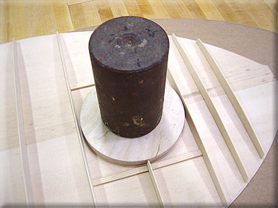
The shams, pickguard and bridge glued in place.


-Braces
A small setback delayed construction for a week. Hankey’s book was a bit confusing concerning the grain orientation for the braces. I made the mistake of misinterpreting his description. Consequently I ordered the wrong wood for the braces weeks ago. (Richard Hankey has since issued an update for the book and clarified the language.) However, I received shipment today of new bracewood. The grain in the braces is quartersawn, but since the brace is taller than it is wide, it appears that the wood is flat sawn because it is parallel with the wide face of the brace. It is actually not flatsawn since ideally the bracewood is split from a billet of spruce, the grain in the brace being perpendicular to the soundboard gluing surface. So a conventionally flatsawn board, from the edge of the tree for example, would not be the best choice since the growth rings would be more curved than straight and perpendicular. There is no word to describe this configuration that I know of.

Shooting board for the top edges of the braces. #7 Stanley jointer plane.

The braces are planed to thickness. Here I have cut the braces to rough length and am comparing them to a paper template/diagram of the brace layout.

After the braces are cut to rough length they are planed on each side to a taper so they are slightly narrower in the middle than at the ends.

Fitting the braces. A straightedge is placed across the back at the braces locations and the angle measurement taken with a small bevel.

After the bevel is transferred to the end of the brace, I clamp it to the straightedge and line the mark up with the inside of the top rib and trace the rib profile from underneath. I repeated this at the other end and cut the brace to length a bit away from the marks. I trimmed the brace to fit with a block plane and file removing small amounts until the brace fit snug, but did not push the top ribs out at all.

A fitted brace taped in position.

Seven braces fitted. The eighth brace is broken by the soundhole and is fitted and glued later.

In order the glue the braces to the back of the soundboard, they must be aligned exactly. I used the glued joint in the soundboard when I layed out the brace locations to begin with since it runs dead center down the soundboard. This straightedge allows me to mark the exact center of each brace so I can glue it to the soundboard exactly. This eliminates any need for measuring or calculations which can cause mistakes, at least in my experience.
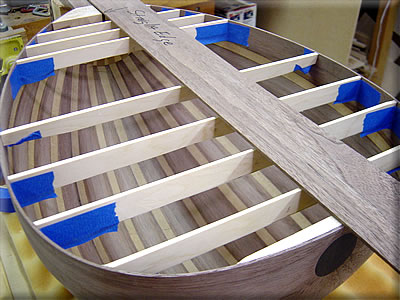
The braces around the bridge are raised above the edge relief to bring the bridge up to the height of the neck. I clamped a wide straightedge to the neck and raised the braces up to the straightedge. I used a wide board in order to help keep the braces parallel to the neck and each other. The second brace between the bridge and the soundhole is only raised to half the height in order to allow the soundboard to dip down with the edge relief. I taped a little piece of wood to the straightedge half the thickness of the gap to establish this distance. Further details are in Hankey’s book.

I made a little scratch with an Exacto knife at the end of the braces to mark how much material to be removed. The brace is only tapered down at the ends. The center is left flat for the bridge to rest on.

Gluing the braces to the soundboard. A protective board, thin and flexible, is under the soundboard to protect it from the clamps.

All the braces, save the ones about the soundhole, glued on.

I made the mistake of not using the protective board for one of the braces and suffered the consequences. It seems one of the clamps made a small divot in the soundboard. It is barely noticeable except under raking light, as here. To the hand it feels like a spot that was sanded a bit too much, and hardly at that. I suppose I could remove the brace and try to steam it flat, and I may do that, but I can also live with this little mistake. I can’t imagine it would be detrimental to the sound.

The spot under normal lighting conditions. Unnoticeable.

Shaping the braces with small plane, chisel and sandpaper. Here I am holding a sanding stick (sandpaper adhered to a scrap of rib stock–thin and flexible) and running my thumb against the opposite side if the brace. The braces are shaped to a thin edge.

Braces after shaping.

The completed bracing.


http://www.khalafoud.com/Jameel_OudConstruction.htm




The amazing and complex beauty of this piece of art is almost incomprehensible.
But nearly as incomprehensible is the skill and patience it takes to create it… I cannot imagine myself.
Je me suis lancé dans la construction d’un Oud mais je n’ai pas le niveau technique que vous avez. Vos explications et vos photos vont m’aider fortement. Votre travail est magnifique, félicitation. La fabrication de la rosace est hallucinante.. Encore bravo..